Friday, 7 June 2024

Create an Azure DNS Private Resolver using the Azure portal


Create an Azure DNS Private Resolver using the Azure portal

This quickstart walks you through the steps to create an Azure DNS Private Resolver using the Azure portal. If you prefer, you can complete this quickstart using Azure PowerShell.

Azure DNS Private Resolver enables you to query Azure DNS private zones from an on-premises environment, and vice versa, without deploying VM based DNS servers. You no longer need to provision IaaS based solutions on your virtual networks to resolve names registered on Azure private DNS zones. You can configure conditional forwarding of domains back to on-premises, multicloud and public DNS servers. For more information, including benefits, capabilities, and regional availability, see What is Azure DNS Private Resolver.

In this article:

  • Two VNets are created: myvnet and myvnet2.
  • An Azure DNS Private Resolver is created in the first VNet with an inbound endpoint at 10.10.0.4.
  • A DNS forwarding ruleset is created for the private resolver.
  • The DNS forwarding ruleset is linked to the second VNet.
  • Example rules are added to the DNS forwarding ruleset.

This article doesn't demonstrate DNS forwarding to an on-premises network. For more information, see Resolve Azure and on-premises domains.

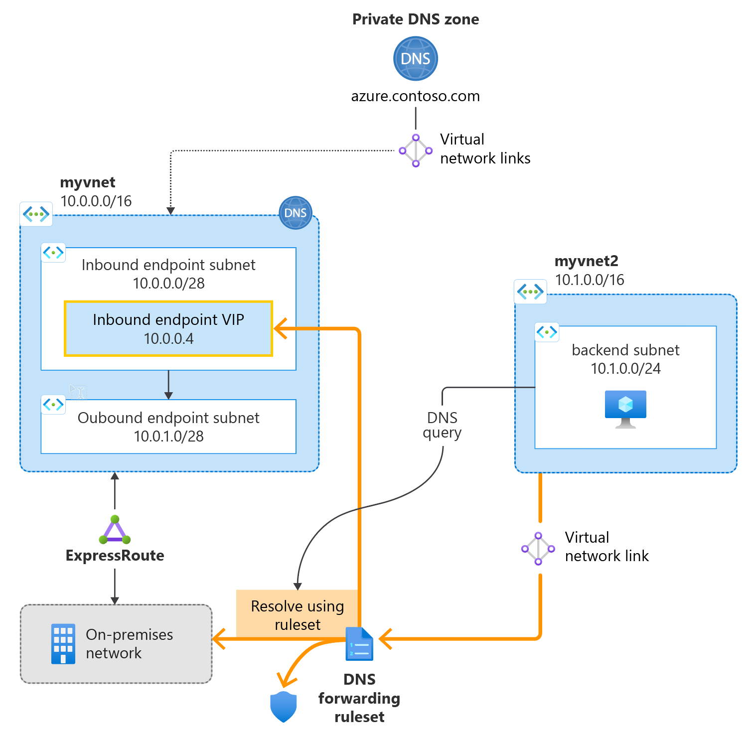
The following figure summarizes the setup used in this article:

Conceptual figure displaying components of the private resolver.

Prerequisites

An Azure subscription is required.

  • If you don't already have an Azure subscription, you can create a free account.

Register the Microsoft.Network provider namespace

Before you can use Microsoft.Network services with your Azure subscription, you must register the Microsoft.Network namespace:

  1. Select the Subscription blade in the Azure portal, and then choose your subscription.
  2. Under Settings select Resource Providers.
  3. Select Microsoft.Network and then select Register.

Create a resource group

First, create or choose an existing resource group to host the resources for your DNS resolver. The resource group must be in a supported region. In this example, the location is West Central US. To create a new resource group:

  1. Select Create a resource group.

  2. Select your subscription name, enter a name for the resource group, and choose a supported region.

  3. Select Review + create, and then select Create.
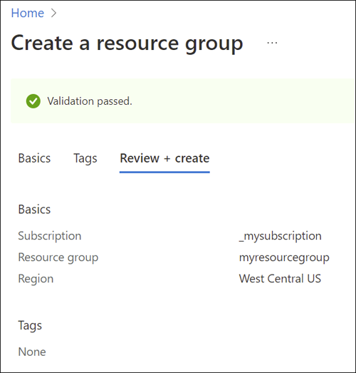
    create resource group

Create a virtual network

Next, add a virtual network to the resource group that you created, and configure subnets.

  1. Select the resource group you created, select Create, select Networking from the list of categories, and then next to Virtual network, select Create.

  2. On the Basics tab, enter a name for the new virtual network and select the Region that is the same as your resource group.

  3. On the IP Addresses tab, modify the IPv4 address space to be 10.0.0.0/8.

  4. Select Add subnet and enter the subnet name and address range:

    • Subnet name: snet-inbound
    • Subnet address range: 10.0.0.0/28
    • Select Add to add the new subnet.
  5. Select Add subnet and configure the outbound endpoint subnet:

    • Subnet name: snet-outbound
    • Subnet address range: 10.1.1.0/28
    • Select Add to add this subnet.
  6. Select Review + create and then select Create.
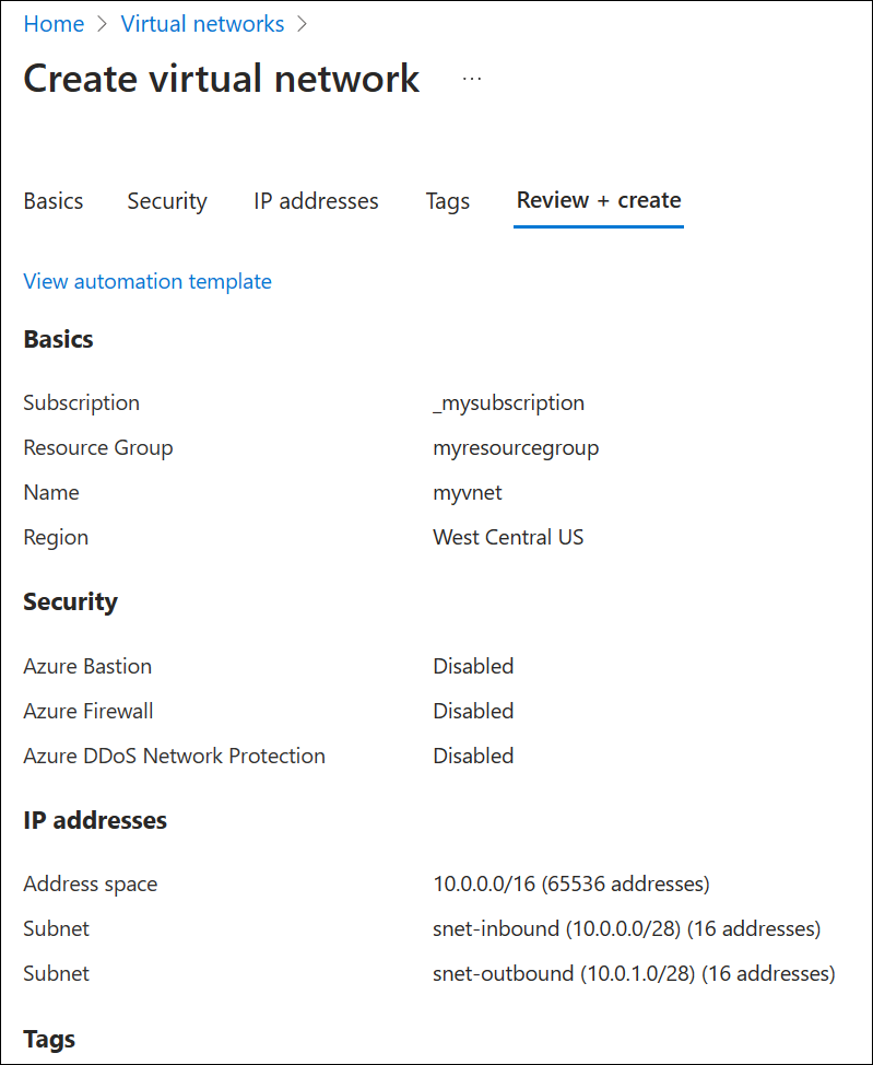
    create virtual network

Create a DNS resolver inside the virtual network

  1. Open the Azure portal and search for DNS Private Resolvers.

  2. Select DNS Private Resolvers, select Create, and then on the Basics tab for Create a DNS Private Resolver enter the following:

    • Subscription: Choose the subscription name you're using.
    • Resource group: Choose the name of the resource group that you created.
    • Name: Enter a name for your DNS resolver (ex: mydnsresolver).
    • Region: Choose the region you used for the virtual network.
    • Virtual Network: Select the virtual network that you created.

    Don't create the DNS resolver yet.
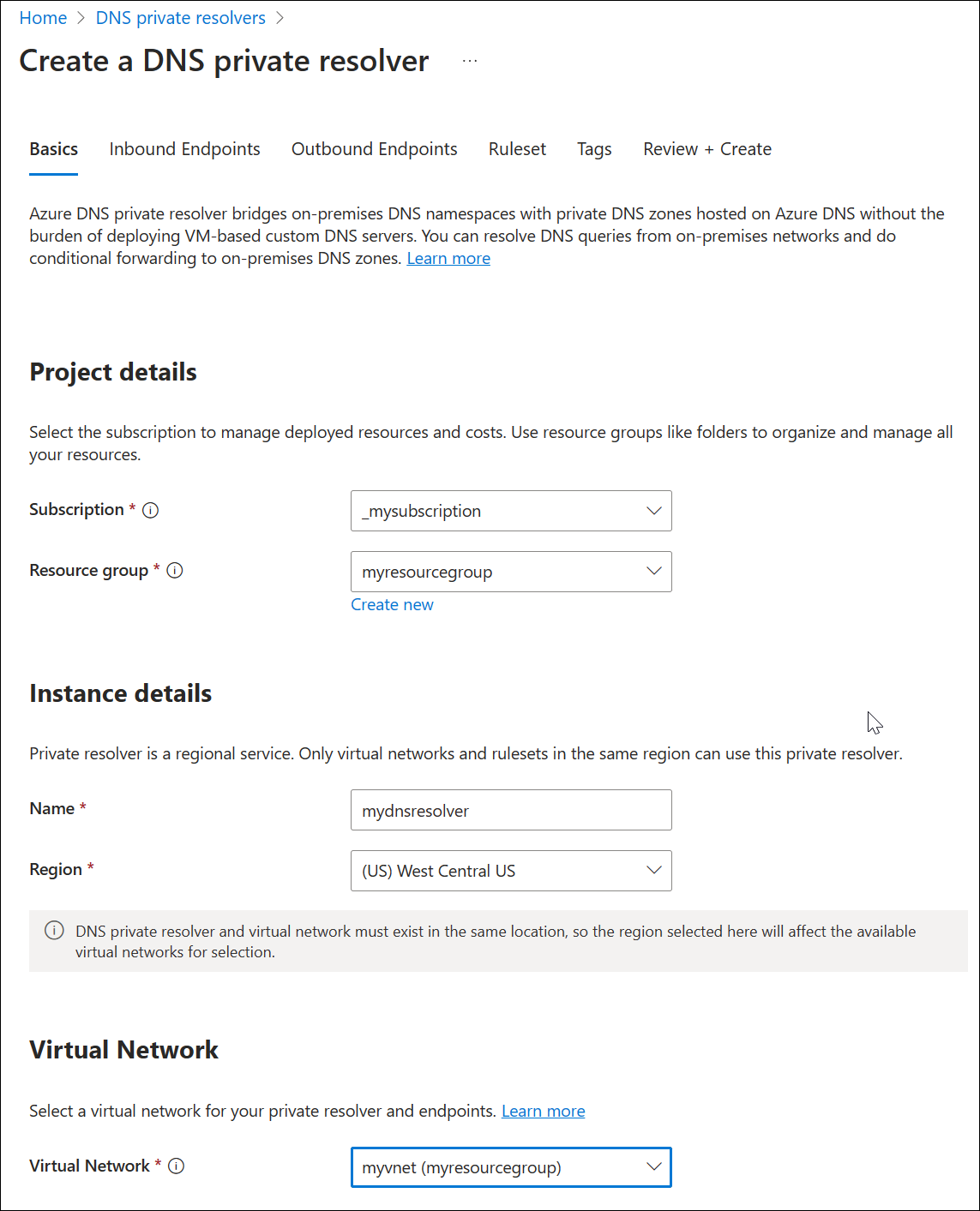
    create resolver - basics

  3. Select the Inbound Endpoints tab, select Add an endpoint, and then enter a name next to Endpoint name (ex: myinboundendpoint).

  4. Next to Subnet, select the inbound endpoint subnet you created (ex: snet-inbound, 10.0.0.0/28) and then select Save.

  5. Select the Outbound Endpoints tab, select Add an endpoint, and then enter a name next to Endpoint name (ex: myoutboundendpoint).

  6. Next to Subnet, select the outbound endpoint subnet you created (ex: snet-outbound, 10.1.1.0/28) and then select Save.

  7. Select the Ruleset tab, select Add a ruleset, and enter the following:

    • Ruleset name: Enter a name for your ruleset (ex: myruleset).
    • Endpoints: Select the outbound endpoint that you created (ex: myoutboundendpoint).
  8. Under Rules, select Add and enter your conditional DNS forwarding rules. For example:

    • Rule name: Enter a rule name (ex: contosocom).
    • Domain Name: Enter a domain name with a trailing dot (ex: contoso.com.).
    • Rule State: Choose Enabled or Disabled. The default is enabled.
    • Select Add a destination and enter a desired destination IPv4 address (ex: 11.0.1.4).
    • If desired, select Add a destination again to add another destination IPv4 address (ex: 11.0.1.5).
    • When you're finished adding destination IP addresses, select Add.
  9. Select Review and Create, and then select Create.
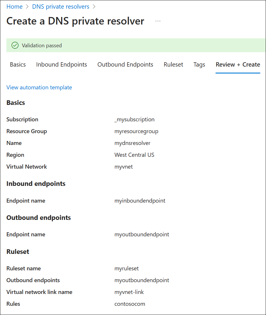
    create resolver - ruleset

    This example has only one conditional forwarding rule, but you can create many. Edit the rules to enable or disable them as needed.
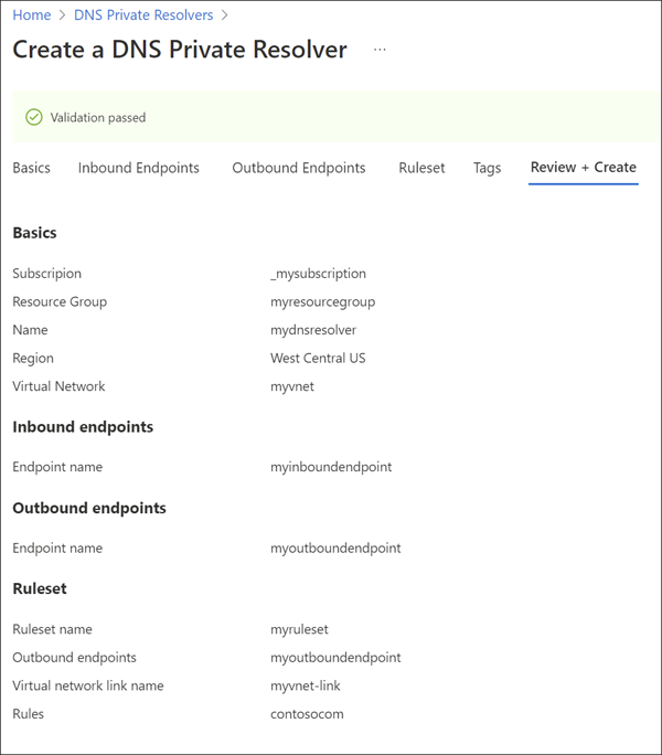
    Screenshot of Create resolver - review.

    After selecting Create, the new DNS resolver will begin deployment. This process might take a minute or two. The status of each component is displayed during deployment.
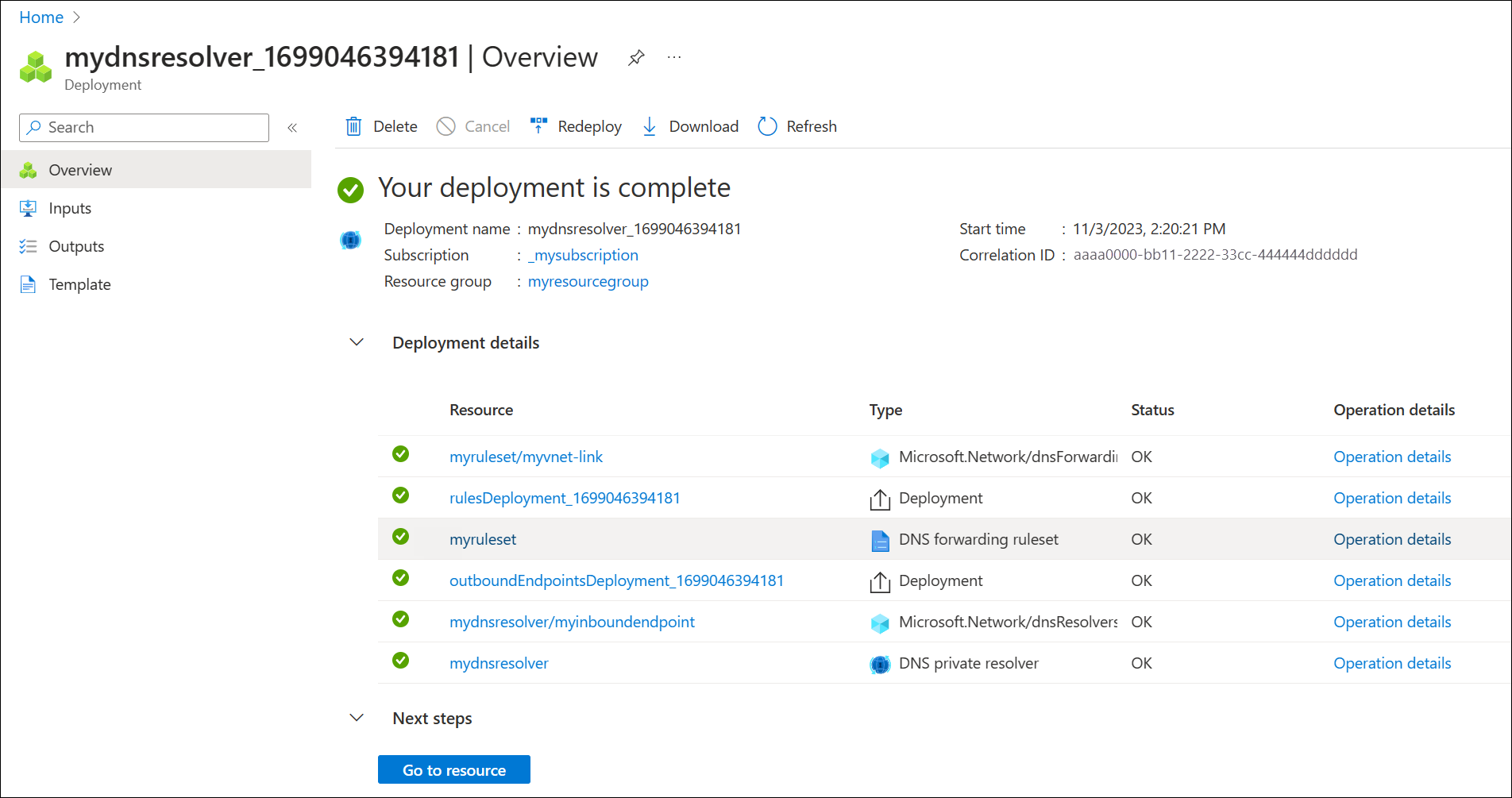
    create resolver - status

Create a second virtual network

Create a second virtual network to simulate an on-premises or other environment. To create a second virtual network:

  1. Select Virtual Networks from the Azure services list, or search for Virtual Networks and then select Virtual Networks.

  2. Select Create, and then on the Basics tab select your subscription and choose the same resource group that you have been using in this guide (ex: myresourcegroup).

  3. Next to Name, enter a name for the new virtual network (ex: myvnet2).

  4. Verify that the Region selected is the same region used previously in this guide (ex: West Central US).

  5. Select the IP Addresses tab and edit the default IP address space. Replace the address space with a simulated on-premises address space (ex: 12.0.0.0/8).

  6. Select Add subnet and enter the following:

    • Subnet name: backendsubnet
    • Subnet address range: 12.2.0.0/24
  7. Select Add, select Review + create, and then select Create.
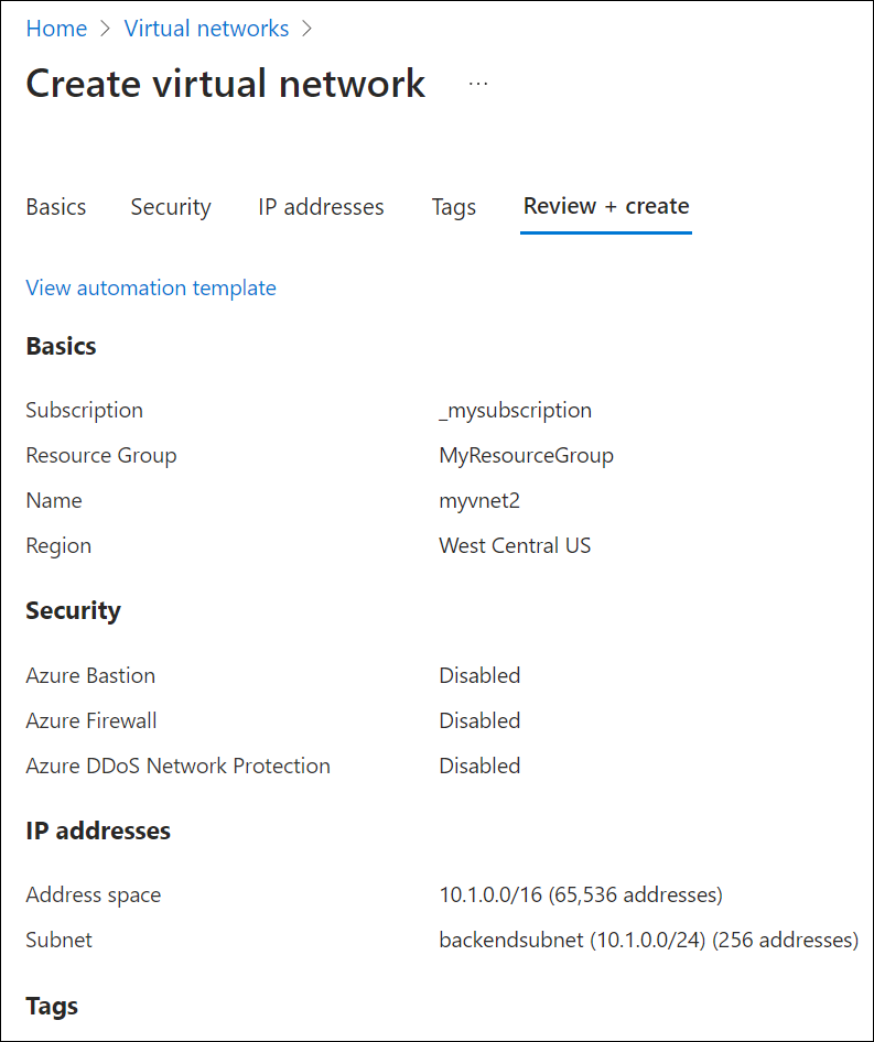
    Screenshot showing creation of a second vnet.

To apply your forwarding ruleset to the second virtual network, you must create a virtual link.

  1. Search for DNS forwarding rulesets in the Azure services list and select your ruleset (ex: myruleset).

  2. Select Virtual Network Links, select Add, choose myvnet2 and use the default Link Name myvnet2-link.

  3. Select Add and verify that the link was added successfully. You might need to refresh the page.
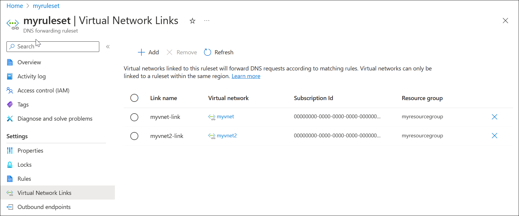
    Screenshot of ruleset virtual network links.

Later in this article a rule is created using the private resolver inbound endpoint as a destination. This configuration can cause a DNS resolution loop if the VNet where the resolver is provisioned is also linked to the ruleset. To fix this issue, remove the link to myvnet.

  1. Search for DNS forwarding rulesets in the Azure services list and select your ruleset (ex: myruleset).

  2. Select Virtual Network Links, choose myvnet-link, select Remove and select OK.
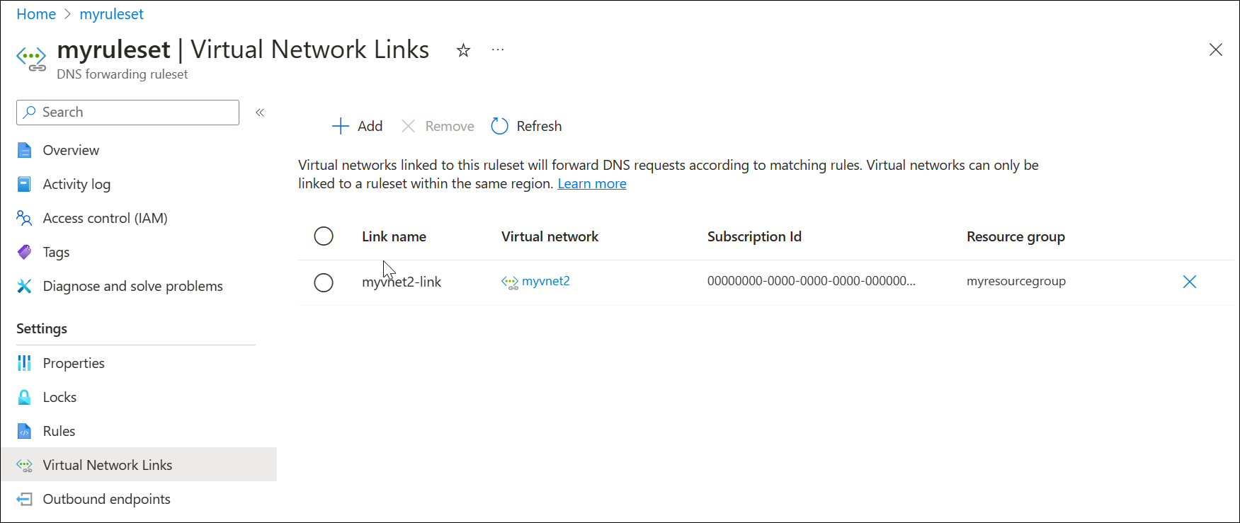
    Screenshot of ruleset virtual network links after removing a link.

Configure a DNS forwarding ruleset

Add or remove specific rules your DNS forwarding ruleset as desired, such as:

  • A rule to resolve an Azure Private DNS zone linked to your virtual network: azure.contoso.com.
  • A rule to resolve an on-premises zone: internal.contoso.com.
  • A wildcard rule to forward unmatched DNS queries to a protective DNS service.

 Important

The rules shown in this quickstart are examples of rules that can be used for specific scenarios. None of the fowarding rules described in this article are required. Be careful to test your forwarding rules and ensure that the rules don't cause DNS resolution issues.

If you include a wildcard rule in your ruleset, ensure that the target DNS service can resolve public DNS names. Some Azure services have dependencies on public name resolution.

Delete a rule from the forwarding ruleset

Individual rules can be deleted or disabled. In this example, a rule is deleted.

  1. Search for Dns Forwarding Rulesets in the Azure Services list and select it.
  2. Select the ruleset you previously configured (ex: myruleset) and then select Rules.
  3. Select the contosocom sample rule that you previously configured, select Delete, and then select OK.

Add rules to the forwarding ruleset

Add three new conditional forwarding rules to the ruleset.

  1. On the myruleset | Rules page, select Add, and enter the following rule data:

    • Rule Name: AzurePrivate
    • Domain Name: azure.contoso.com.
    • Rule State: Enabled
  2. Under Destination IP address enter 10.0.0.4, and then select Add.

  3. On the myruleset | Rules page, select Add, and enter the following rule data:

    • Rule Name: Internal
    • Domain Name: internal.contoso.com.
    • Rule State: Enabled
  4. Under Destination IP address enter 192.168.1.2, and then select Add.

  5. On the myruleset | Rules page, select Add, and enter the following rule data:

    • Rule Name: Wildcard
    • Domain Name: . (enter only a dot)
    • Rule State: Enabled
  6. Under Destination IP address enter 10.5.5.5, and then select Add.
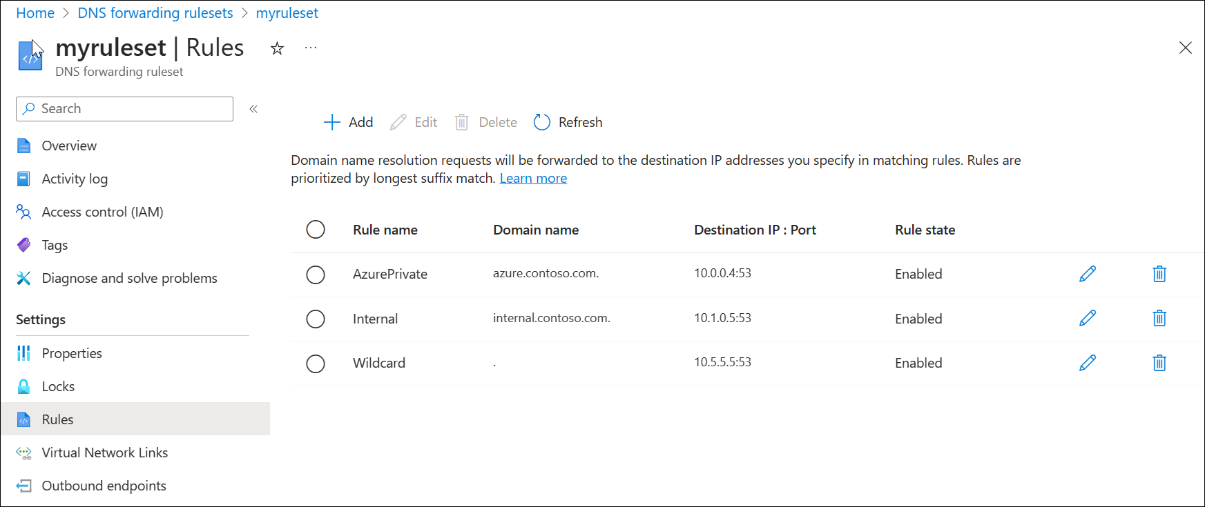
    Screenshot of a forwarding ruleset example.

Wednesday, 5 June 2024

Configuring Site to Site VPN tunnels to Azure VPN Gateway


Configuring Site to Site VPN tunnels to Azure VPN Gateway

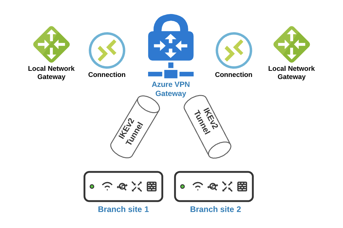
Architecture

Screen Shot 2020-08-27 at 3.09.30 PM.png

Prerequisites

  • Each branch MX must be on firmware 15 or greater to take advantage of IKEv2.
  • Virtual Network (VNET) with GatewaySubnet subnet.

Deployment Steps

To establish an IPSec tunnel to Azure, configurations must be made on both Azure Portal and Meraki Dashboard.


Azure Portal 

Deploy Azure Virtual Network Gateway (if one is not created)

  • In the Azure portal, in the Search the Marketplace field, type 'Virtual Network Gateway'. Locate Virtual network gateway in the search return and select the entry. On the Virtual network gateway page, select Create. This opens the Create virtual network gateway page.
  • On the Basics tab, fill in the values for your virtual network gateway.

Virtual Network Gateway Configuration (1).png

Deploy Azure Local Network Gateway 

You give the site a name by which Azure can refer to it, then specify the IP address of the on-premises VPN device to which you will create a connection. You also specify the IP address prefixes that will be routed through the VPN gateway to the VPN device. The address prefixes you specify are the prefixes located on your on-premises network. If your on-premises network changes or you need to change the public IP address for the VPN device, you can easily update the values later.

  • From the Azure portal menu, select Create a resource

  • In the Search the marketplace field, type Local network gateway, then press Enter to search. This will return a list of results. Click Local network gateway, then click the Create button to open the Create local network gateway page

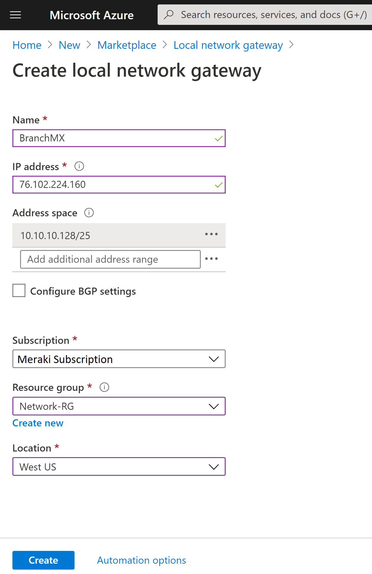
  • On the Create local network gateway page, specify the values for your local network gateway.

    • Name: Specify a name for your MX branch site.
    • IP address: This is the public IP address of the MX device, which can be found under the appliance status page in dashboard. 
    • Address Space refers to the address ranges for the network that this local network represents. This is located under the addressing and vlans page on the Meraki dashboard. 
    • Subscription: Verify that the correct subscription is showing.
    • Resource Group: Select the resource group that you want to use. You can either create a new resource group, or select one that you have already created.
    • Location: The location is the same as Region in other settings. Select the location that this object will be created in. You may want to select the same location that your VNet resides in, but you are not required to do so.

Azure Local Network Gateway.png

  • When you have finished specifying the values, click the Create button at the bottom of the page to create the local network gateway.

Configure the MX Security Appliance VPN information

  • A shared key. This is the same shared key that you specify when creating your Site-to-Site VPN connection. In our examples, we use a basic shared key. We recommend that you generate a more complex key to use.
  • The Public IP address of your virtual network gateway. You can view the public IP address by using the Azure portal, PowerShell, or CLI. To find the Public IP address of your VPN gateway using the Azure portal, navigate to Virtual network gateways, then click the name of your gateway.
  • In addition, you will need to specify the vnet subnets under the private subnet field in the Meraki dashboard located on the site to site vpn page. 

Screen Shot 2020-08-31 at 5.25.19 PM.png

Create connection resource

Create the Site-to-Site VPN connection between your virtual network gateway and your on-premises VPN device.

  • Open the page for your virtual network gateway. There are multiple ways to navigate. You can navigate to the gateway by going to Name of your VNet -> Overview -> Connected devices -> Name of your gateway.

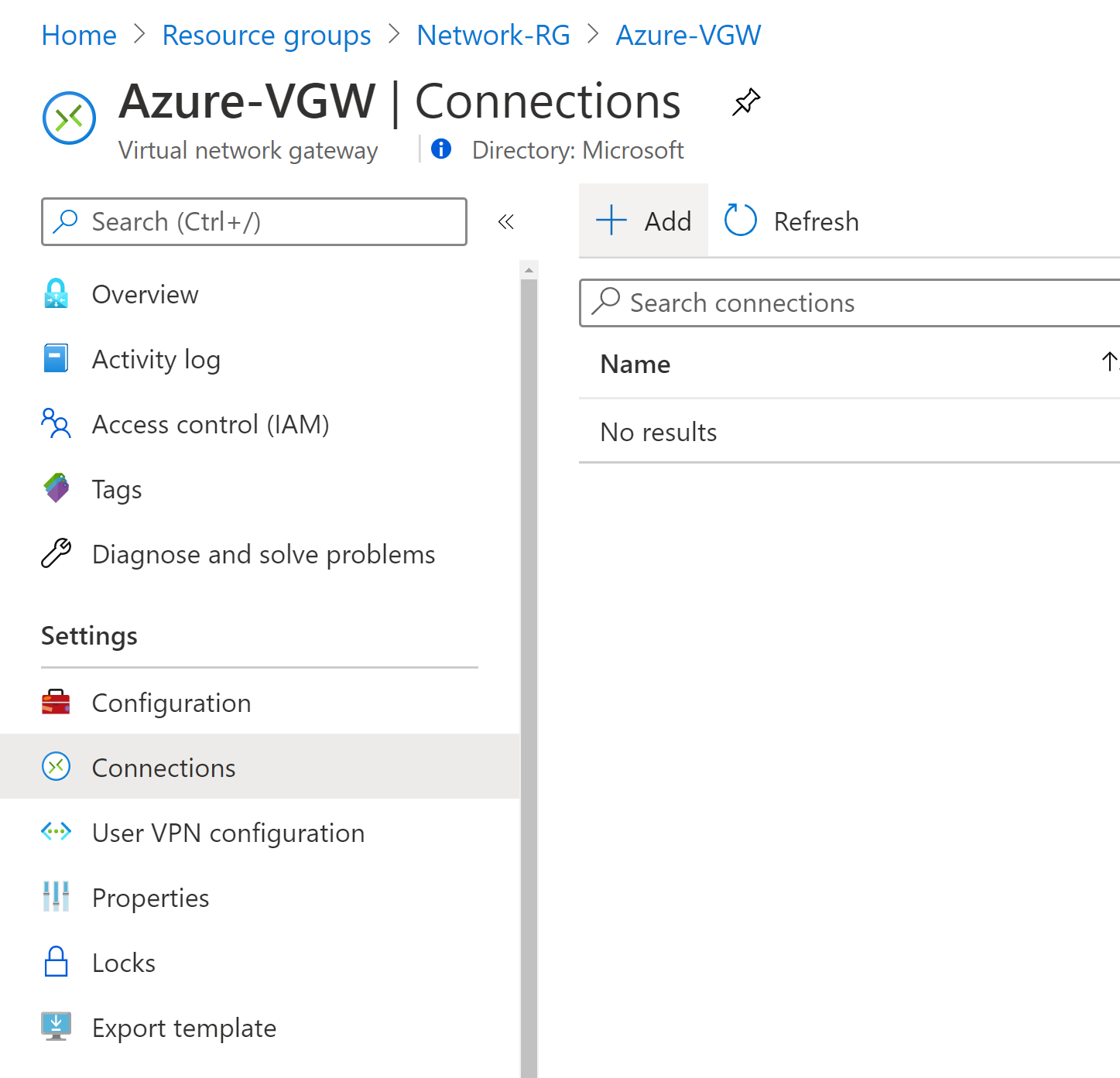
  • On the page for the gateway, click Connections. At the top of the Connections page, click +Add to open the Add connection page

Add Connection.png

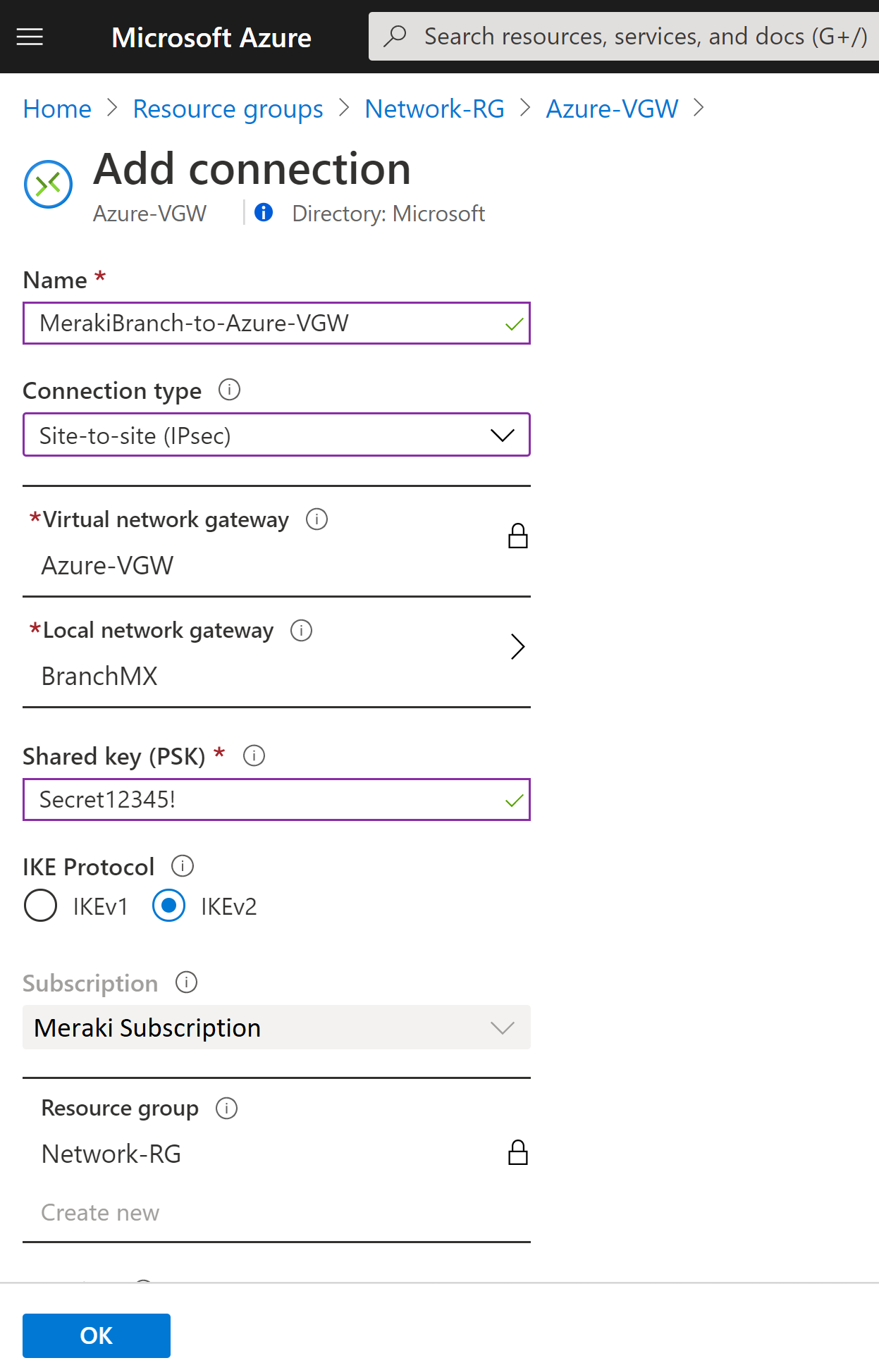
  • On the Add connection page, configure the values for your connection.

    • Name: Name your connection.
    • Connection type: Select Site-to-site(IPSec).
    • Virtual network gateway: The value is fixed because you are connecting from this gateway.
    • Local network gateway: Click Choose a local network gateway and select the local network gateway that you want to use.
    • Shared Key: the value here must match the value that you are using for your local on-premises VPN device. The example uses 'Secret12345!', but you can (and should) use something more complex. The important thing is that the value you specify here must be the same value that you specify when configuring your VPN device.
    • IKE Protocol: Select IKEv2
    • The remaining values for SubscriptionResource Group, and Location are fixed.

Add Connection - MerakiBranch.png

  • Click OK to create your connection. You'll see Creating Connection flash on the screen.

  • You can view the connection in the Connections page of the virtual network gateway. The Status will go from Unknown to Connecting, and then to Succeeded.


Verify the VPN connection

In the Azure portal, you can view the connection status of a Resource Manager VPN Gateway by navigating to the connection. The following steps show one way to navigate to your connection and verify.

  1. In the Azure portal menu, select All resources or search for and select All resources from any page.

  2. Select to your virtual network gateway.

  3. On the blade for your virtual network gateway, click Connections. You can see the status of each connection.

  4. Click the name of the connection that you want to verify to open Essentials. In Essentials, you can view more information about your connection. The Status is 'Succeeded' and 'Connected' when you have made a successful connection.


In the Meraki dashboard, each Meraki network has its own event log, accessible under Network-wide > Monitor > Event log. In a combined network, click the drop-down menu at the top of the page and select the event log for one of the following options:

  • for security appliances to display information about the MX security appliance in this network.

Once there, you will be able to verify that the IKEv2 tunnel was established with a timestamp as seen below:

Screen Shot 2020-08-31 at 5.58.44 PM.png


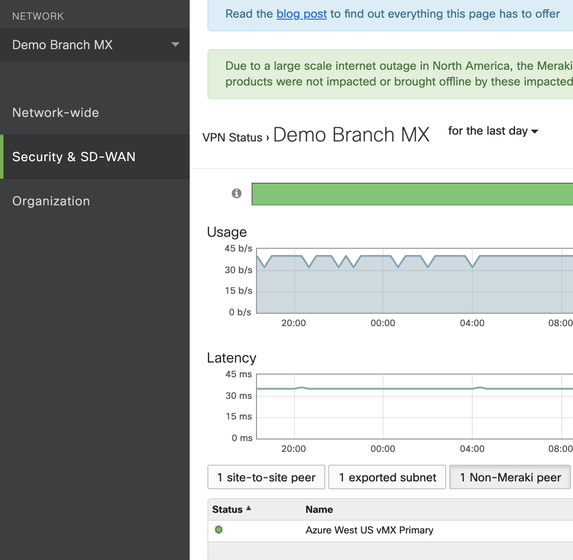
Additionally, you can access the VPN Status page by navigating to the Organization > Monitor > VPN Status tab, or by navigating to the Security & SD-WAN > Monitor > VPN Status tab. On the non-Meraki peers tab, the following information is available:

  • Status - whether the peer is currently reachable or not.

  • Name - Name of the non-Meraki peer configured on the Security & SD-WAN > Configure > Site-to-Site VPN page.

  • Public IP - Pubic IP configured for the non-Meraki VPN peer.

  • Subnets - All subnets configured under the "Remote Subnets" field on the Security & SD-WAN > Configure > Site-to-Site VPN page.

Screen Shot 2020-08-31 at 6.02.33 PM.png


Criando um Public IP Prefixes na Azure

Criando um Public IP Prefixes na Azure

O tema de hoje é sobre como estar Criando um Public IP Prefixes na Azure.

Caro leitor, antes de tudo seja bem-vindo ao Blog Jefferson Castilho.

Neste artigo vou mostrar como podemos uma estrutura de Prefixos de IP dentro da Azure.

Como que funciona a estrutura de Prefixos de IPS na Azure, Você pode usar de duas forma ou para um unico IP Publico ou para um Range de IP´s que serão alocados para você.

No /28 temos 16 ips que no exemplo

No processo de alocação podemos fazer ele de algumas formas, entre elas usamos os barramentos por exemplo.

  • /28 – Com 16 IP´s por exemplo temos 200.200.200.200 até o 216
  • /29 – Com 8 IP´s por exemplo temos 200.200.200.200 até o 208
  • /30 – Com 4 IP´s por exemplo temos 200.200.200.200 até o 204
  • /31 – Com 2 IP´s por exemplo temos 200.200.200.200 até o 202

Recurso já disponível com o IPV6.

Assim podemos ter mais IP´s em nossa infraestrutura. Temos um ponto importante que podemos usar um IP´s que seja nosso usando a opção Custom IP Prefix (BYOIP)

Para saber mais clique no link abaixo.


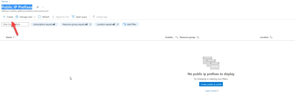
Para efetuar a criacao temos que selecionar a opção “Public IP Prefixes” no menu de busca de produto do Azure, opção “Create”.

criando_um_public_ip_prefixes_na_azure_06

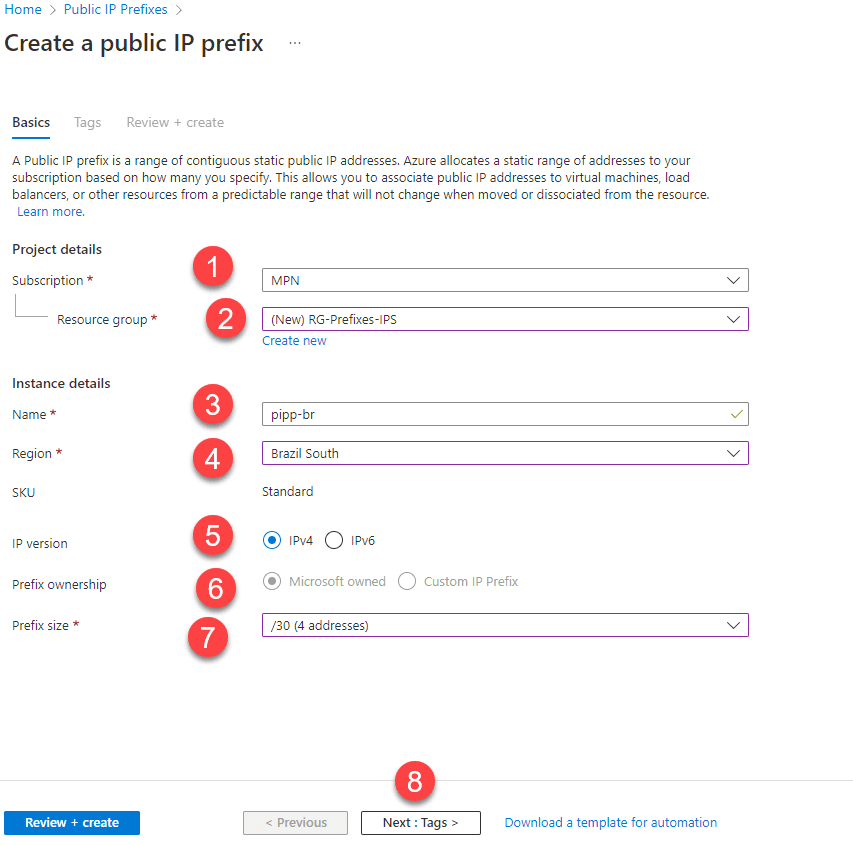
No processo de criação do public ip prefixes temos alguns step que serão necessarios para a efetividade do serviço

  1. Assinatura que deseja incluir o serviço.
  2. Criar ou usar um Resource group existente.
  3. Nome do recurso.
  4. Region que deseja criar o prefixo de ip.
  5. Versão do IP, em nosso caso iremos utilizar o IPV4.
  6. Em Prefix ownership iremos utilizar o provido pela Microsoft, mais neste caso foi o que eu citei no artigo acima com a questão de ter seu próprio IP Address na Azure.
  7. A quantidade de IP´s que desejamos em nosso caso de exemplo iremos usar um /30.
  8. Próximo passos para obter a criação.
Criando um Public IP Prefixes na Azure

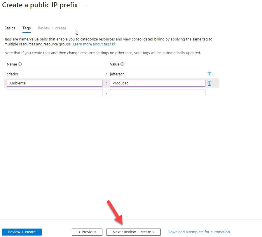
Neste passo iremos utilizar as tags do ambientes.

Criando um Public IP Prefixes na Azure

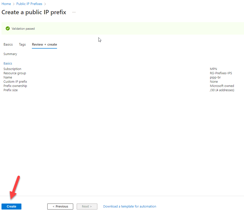
Caso esteja tudo certo podemos selecionar a opção de “Create”.

Criando um Public IP Prefixes na Azure

Após isso teremos o recurso provisionado com sucesso.

Terminando de acordo que é provável que conhece as minhas redes sociais.

Step by Step Azure NAT Gateway – Static Outbound Public IP address

Step by Step Azure NAT Gateway – Static Outbound Public IP address #ANG #NAT #WVD #Azure #Security #Cloud #MVPBuzz #AzOps #ITPRO #VirtualNetworks #PowerShell

There a several ways on using an external IP in Azure, What method to use is up to you. Remember there is no good or wrong but only different opinions or insights on how to use it.

Public IP addresses allow Internet resources to communicate inbound to Azure resources. Public IP addresses also enable Azure resources to communicate outbound to Internet and public-facing Azure services with an IP address assigned to the resource. The address is dedicated to the resource, until it is unassigned by you. If a public IP address is not assigned to a resource, the resource can still communicate outbound to the Internet, but Azure dynamically assigns an available IP address that is not dedicated to the resource.

Some of the resources you can associate a public IP address resource with are:

  • Virtual machine network interfaces
  • Internet-facing load balancers
  • VPN gateways
  • Application gateways
  • Azure Firewall
  • NAT Gateway

Matching SKUs must be used for load balancer and public IP resources. You can’t have a mixture of basic SKU resources and standard SKU resources. You can’t attach standalone virtual machines, virtual machines in an availability set resource, or a virtual machine scale set resources to both SKUs simultaneously.

Virtual Network NAT (network address translation) simplifies outbound-only Internet connectivity for virtual networks. When configured on a subnet, all outbound connectivity uses your specified static public IP addresses. Outbound connectivity is possible without load balancer or public IP addresses directly attached to virtual machines. NAT is fully managed and highly resilient.

image

So this is only for the Outbound connection. why not use the Resource group IP this is also “static” ? using this IP means that al VM’s must be in the same resource group and when the resource group changed the IP is also changing.

image

NAT is compatible with standard SKU public IP address resources or public IP prefix resources or a combination of both. You can use a public IP prefix directly or distribute the public IP addresses of the prefix across multiple NAT gateway resources. NAT will groom all traffic to the range of IP addresses of the prefix. Any IP whitelisting of your deployments is now easy.

So How to implement this. a step by step guide. GUI and powershell Looking at my demo setup, There are 2 vm’s both in a different Resource group.

Setting up the NAT gateway is done by 3 tabs to fill in the name and what vnet to use

https://robertsmit.wordpress.com/

We add a new NAT gateway.

image

We create a new resource group and choose NAT gateway name.

The Timeout we leave this on 4 min for now.

image

We configure an external IP and with a standard SKU. Basic is not supported.

image

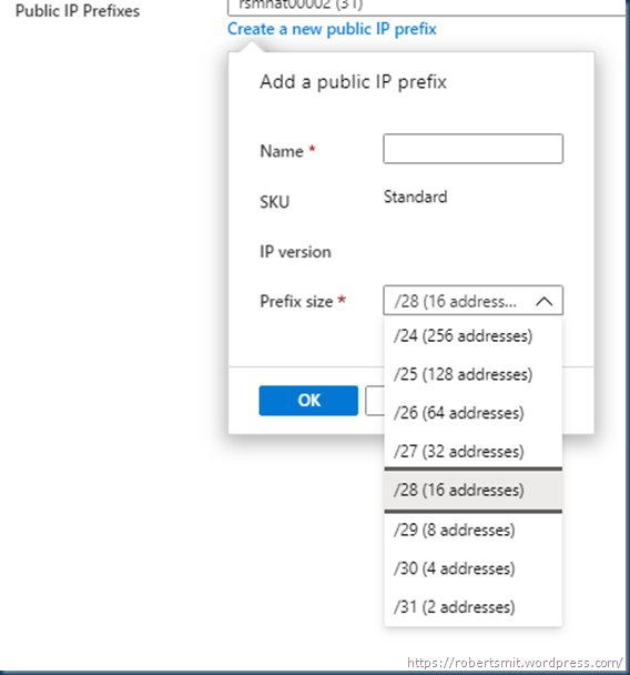
the next step is choose the External outbound IP pool minimal is 2 and max is 256. this is not needed but only if you want to have a pool of External IP’s else it just go the one external ip

image

you can select max 2 prefixes

image

Configure which subnets of a virtual network should use this NAT gateway. Subnets with Basic load balancers or virtual machines that are using a Basic public IP are not compatible and cannot be used.
Note: While you do not have to complete this step to create a NAT gateway, the NAT gateway will not be functional until you have added at least one subnet. You can also add and reconfigure which subnets are included after creating the NAT gateway.

image

in the last step we tag the NAT gateway to a subnet. When checking the VM’s on this subnet for the outbound IP ( remember the VM does not need a public IP on the network card)

image

Here I have 2 VM’s getting both an IP from the prefix

imageimage

If there is only a small prefix then both machines will get the same external outbound IP

imageimage

With this time flow it recycles the External IP, depending on the scope and usage.

image

So in just a few steps you can use a useful gateway for all your outbound traffic.

Building this in Powershell is also easy. I use a semi automatic script as I want to choose my network. but you can change this to a fixed network if you want.

remember this will need the az.network latest module. in the old modules there is no get-AzNatGateway command. without this the posh is not working.

First we have some parameters

# Set the variables for the NAT Gateway.
$rg = ‘rg-rsm-natgw001’
$Location = ‘Westeurope’
$sku = ‘Standard’
$PublicIpname = ‘pup-rsm-natgw001’
$Publicprefixname = ‘pxp-rsm-natgw001’
$NatGatewayname=’gwn-rsm-natgateway001′

#create Rsource group
New-AzResourceGroup -Name $rg -Location $Location 

VirtualNetwork Service Tag and Network Security Groups


VirtualNetwork Service Tag and Network Security Groups

Earlier this week I was messing around with Kubernetes SSHing into the nodes and I ran into an interesting quirk of NSGs (Network Security Groups). I noticed that traffic I did not expect to be allowed through the NSG was making it through. A bit of digging let me down the path of a documented, but not well known, behavior of the VirtualNetwork service tag when used in NSG security rules. Today I’m going to walk through that behavior, why you should care, and what you can do to avoid being surprised like I was.

NSGs are layer four stateful firewalls that operate at the SDN (software-defined network). They serve a similar purpose and function in much the same way as AWS Security Groups. NSGs are used for microsegmentation within and across Virtual Networks typically supplementing the centralized control that is provided by a security appliance such as Azure Firewall or a Palo Alto firewall. They are associated to a subnet (best practice) or NIC (network interface) (few use cases for this). Each contains a collection of security rules, which includes default rules and user-defined rules. NSG security rules are processed by priority and are matched based on a 5-tuple.

As described in the previous link, service tags can be used within NSG security rules to simplify access to Azure resources. Service tags contain a summarized list of IPs that is managed by Microsoft. This makes life far easier, because whitelisting the IPs to something like Azure Storage Rules would be a nightmarish task that would require customer-created automation to keep up to date as IPs are added or removed to the underlining service. The benefit of service tags does come with a consideration as we’ll see in this post.

Each subnet or NIC can have one NSG applied to it, but the NSG can be applied to multiple subnets or NICs. In the instance of NSGs being applied at both the subnet and NIC, the processing for inbound traffic is detailed here and for outbound here.

Now that you know the basics of NSGs, let me talk a bit about the lab. For this lab I used my simple hub and spoke lab with a few modifications. I have added an Ubuntu VM running in the application subnet (snet-app) in the workload spoke virtual network. I’ve also temporarily removed the UDR from the custom route table on the application subnet. The NSG applied to the spoke contains only the default NSG rules. The lab architecture can be seen below.

Lab environment

Reviewing the NSG applied to the application subnet, the three default inbound rules are present as expected. The rule I’m going to look more deeply at is the AllowVnetInBound rule highlighted below. Specifically, I’m going to show you how to look at the IPs behind a service tag.

Default Inbound NSG Security Rules

To see the IPs associated with a service tag, I’m going to use the Effective security rules tool in Azure’s Network Watcher. If you’re unfamiliar with Network Watcher, you’re missing out. It contains a plethora of useful tools to help diagnose network connectivity. The Effective security rules tool looks at the NSGs applied to a NIC at both the subnet and NIC level to provide you with a holistic view of the what traffic is allowed and combined between NSGs applied at each level.

Effective security rules tool in Network Watcher

One of the lesser known features of the tool is it gives you the ability to look at the IPs included within a service tag for a specific NSG security rule. In the image below you will see that the IPs included in the VirtualNetwork service tag are the workload virtual network IP range (10.2.0.0/16), the peered transit virtual network IP range (10.0.0.0/16), and the Azure “magic IP” 168.63.129.16. This is likely what you expected to see in the VirtualNetwork tag.

VirtualNetwork service tag contents without UDR

Remember when I said I removed the UDR for the default route from the custom route table applied to the application subnet? I then added that route back in, pointed it to the Azure Firewall, waited about 2 minutes, then re-ran the Effective security rules tool.

VirtualNetwork service tag contents with UDR of default route

My first reaction to seeing all IP addresses now allowed through the VirtualNetwork tag was pretty much the Scanners head explosion GIF (classic if you haven’t seen it). It turns out this behavior is documented. The VirtualNetwork service tag has the following explanation:

The virtual network address space (all IP address ranges defined for the virtual network), all connected on-premises address spaces, peered virtual networks, virtual networks connected to a virtual network gateway, the virtual IP address of the host, and address prefixes used on user-defined routes. This tag might also contain default routes.

https://docs.microsoft.com/en-us/azure/virtual-network/service-tags-overview#available-service-tags

The part of that excerpt you need to care about is the piece about it includes the address prefixes on user-defined routes. This means that the prefixes in the UDRs you place on a custom route table applied to the subnet are added to the VirtualNetwork service tag in the NSG security rules used by the NSGs applied to your resource. I’m not sure why this behavior was implemented, but it can impact separation of duties where you’d have a networking team managing the routing within route tables and the security team managing which traffic is allowed in or out with NSGs. If someone has control over the routing tables, they can influence the VirtualNetwork service tag prefixes, which will influence the behavior of the default NSG security rules and others using that tag.

If you’re like me, your first level of panic was around the risk of this allowing traffic from the public Internet inbound to the resource if the resource had a public IP. You can rest easy in that my testing showed this is not possible even with an additional UDR in place to assure symmetric flow of traffic to the Internet endpoint coming in directly via the public IP. It’s likely Microsoft is doing some type of filtering at the SDN layer excluding traffic identified as being sourced from the Internet from being included in this security rule.

It gets more interesting when you use the IP Flow Verify tool in Network Watcher. Here I picked a random public IP and tested an inbound flow. The tool reports the flow as being allowed by the default AllowVnetInBound rule. Take note of this behavior because it could lead to confusion with your Information Security team or third-party auditors.

IP Flow Verify showing flow is allowed