Thursday, 8 February 2024

Configuration of an IP Address on a Router Interface: Packet Tracer

 in this article, I describe the Configuration of an IP Address on a Router Interface. Configuring an IP address on a router interface is a fundamental task in network administration and design. Routers play a critical role in directing data traffic between different network segments, and assigning IP addresses to router interfaces is essential for facilitating this communication. In this comprehensive guide, we will explore the step-by-step process of Configuration of an IP Address on a Router Interface.

Types of Router Interfaces

Routers are equipped with multiple interfaces, each representing a physical or logical connection to a specific network segment. These interfaces serve as gateways for data to enter or exit a particular network. Here are some common types of router interfaces:

  1. Ethernet Interfaces: These are used to connect routers to Ethernet LANs, typically using RJ45 connectors. Ethernet interfaces may have various speeds, such as 10/100/1000 Mbps (Fast Ethernet or Gigabit Ethernet).
  2. Serial Interfaces: Serial interfaces are used for connecting routers over WAN links, such as leased lines, T1/E1 lines, or serial cables. They often operate at lower speeds compared to Ethernet interfaces.
  3. Loopback Interfaces: Loopback interfaces are virtual interfaces that allow routers to communicate with themselves. They are often used for diagnostics, management, or as the source IP address for certain services.
  4. Subinterfaces: Subinterfaces are logical divisions of physical interfaces. They are used for segmenting traffic within a single physical interface, often in VLAN (Virtual LAN) or VRF (Virtual Routing and Forwarding) configurations.
  5. Tunnel Interfaces: Tunnel interfaces are used for creating virtual point-to-point or multipoint connections over an existing network, often for VPNs or encapsulation of traffic.

Purpose of Configuration of an IP Address on a Router Interface

Configuration of an IP Address on a Router Interface serves several crucial purposes as following:

  1. Routing: Routers use IP addresses on their interfaces to determine how to route data traffic between networks. Each interface represents a different network segment, and the IP address assigned to it defines the network’s identity.
  2. Network Segmentation: IP addresses on router interfaces allow for network segmentation. By assigning distinct IP address ranges to different interfaces, network administrators can create isolated subnets or VLANs, enhancing network security and performance.
  3. Gateway Functionality: Router interfaces act as gateways for devices within their respective networks. Devices use the router’s IP address on their subnet as the default gateway to reach devices on other networks.
  4. Routing Protocols: When routers communicate with each other to exchange routing information, they use the IP addresses of their interfaces. Configuring IP addresses on router interfaces is essential for enabling dynamic routing protocols like OSPF, EIGRP, or BGP.
  5. Remote Management: Network administrators often access routers remotely for configuration and troubleshooting. Assigning an IP address to a router interface allows remote access via SSH, Telnet, or web-based interfaces.

Step-by-Step Guide to Configuration of an IP Address on a Router Interface

Now, let’s walk through the step-by-step process of Configuration of an IP Address on a Router Interface. We’ll use a Cisco router as an example, but the general principles apply to routers from other manufacturers as well.

1. Access Router CLI

In the packet tracer double-click on router and select the CLI tab.

2. Enter Privileged Exec Mode

Once you’re in the router’s CLI, start by entering privileged exec mode, also known as enable mode. This mode grants you elevated privileges to configure the router:

Router> enable
Router#

You should see a prompt change from Router> to Router#, indicating that you’re in enable mode.


3. Access Global Configuration Mode

From enable mode, access global configuration mode, which is where you configure global settings for the router. Use the configure terminal (or conf t for short) command:

Router# configure terminal
Router(config)#

Your prompt should now change to Router(config)#, indicating that you’re in global configuration mode.

4. Select the Interface to Configure

Identify the interface to which you want to assign an IP address. You can do this by using the show interfaces command, which lists all available interfaces on the router. For example, if you want to configure an Ethernet interface, it might be labeled as GigabitEthernet0/0.

5. Access Interface Configuration Mode

Enter the configuration mode for the chosen interface using the interface command followed by the interface identifier:

Router(config)# interface GigabitEthernet0/0
Router(config-if)#

Your prompt should now show the specific interface you’re configuring, such as Router(config-if)#.

6. Assign an IP Address

With the interface configuration mode active, assign an IP address to the interface using the ip address command. Specify the IP address followed by the subnet mask:

Router(config-if)# ip address 192.168.1.1 255.255.255.0

In this example, we’ve assigned the IP address 192.168.1.1 to the interface with a subnet mask of 255.255.255.0.

7. Enable the Interface

Activate the interface by using the no shutdown command. This command ensures that the interface is operational and can transmit and receive data:

Router(config-if)# no shutdown

8. Exit Interface Configuration Mode

Exit the interface configuration mode to return to global configuration mode:

Router(config-if)# exit
Router(config)#

9. Save Configuration

To ensure that your configuration persists after a router reboot, save it to non-volatile memory using the write memory (or copy running-config startup-config or wr for short) command:

Router(config)# end
Router# write memory
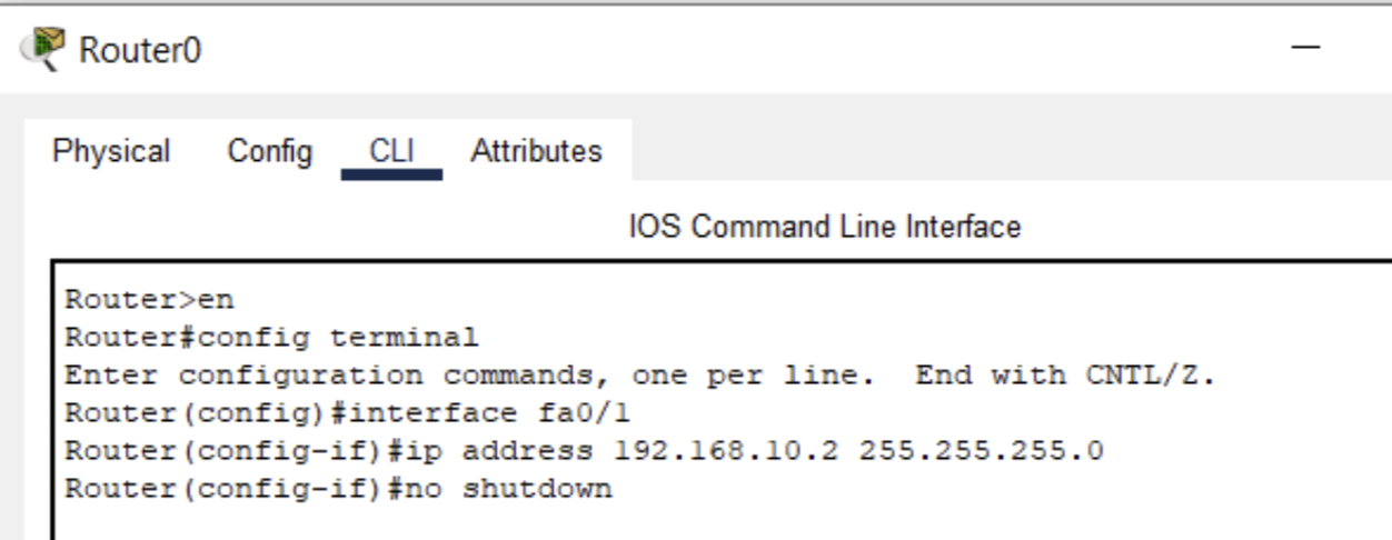
Configuration of an IP Address on a Router Interface, ccna, ccna tutorials

Verification and Testing of Configuration of an IP Address on a Router Interface

After configuring the IP address on the router interface, it’s crucial to verify the configuration to ensure it’s correct. You can do this by using various commands, including:

  • show ip interface brief: This command displays a summary of all interfaces and their IP addresses.
  • show interfaces <interface>: Replace <interface> with the specific interface you configured to see detailed information about that interface.
  • ping <ip_address>: Use the ping command to test connectivity to other devices on the same subnet or to remote networks.
  • show ip route: This command displays the routing table, showing the networks the router knows how to reach.
 

By using these commands, you can confirm that the router interface is configured correctly and that it can communicate with other devices on the network.

Additional Considerations for Configuration of an IP Address on a Router Interface

Here are some additional considerations when configuring IP addresses on router interfaces:

  1. Subnet Design: Ensure that the IP addresses you assign to router interfaces are part of the correct subnet design. Proper subnetting is essential for efficient IP address allocation.
  2. Default Gateway: Devices on a subnet need to know the IP address of the router interface on that subnet as their default gateway. Ensure that this information is correctly configured on devices within the subnet.
  3. Security: Consider implementing access control lists (ACLs) on the router interfaces to control inbound and outbound traffic, enhancing network security.
  4. Dynamic Address Assignment: In some cases, you may want to use DHCP (Dynamic Host Configuration Protocol) to dynamically assign IP addresses to devices on a subnet. Ensure that DHCP configured correctly on the router if needed.
  5. Monitoring and Maintenance: Regularly monitor router interfaces for performance, errors, and traffic patterns. Implement a robust maintenance plan to keep router configurations up-to-date and secure.

Conclusion for Configuration of an IP Address on a Router Interface

Configuration of an IP Address on a Router Interface is a fundamental task in network administration. It plays a pivotal role in routing data traffic, facilitating network communication, and defining network boundaries. By following the step-by-step guide outlined in this comprehensive overview, you can effectively configure IP addresses on router interfaces, ensuring that your network operates efficiently and securely. Understanding the importance of this task is essential for network administrators and engineers responsible for maintaining and designing complex network infrastructures. I hope you found this article useful related to the Configuration of an IP Address on a Router Interface.

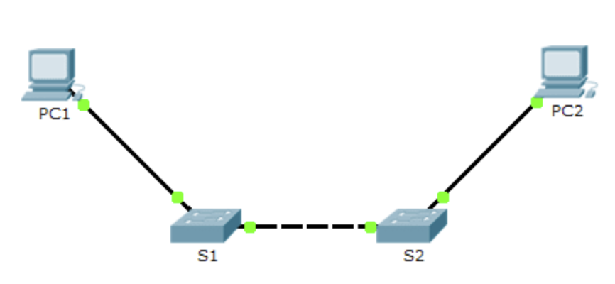
Connecting Two Switches in Packet Tracer

 In this article, I describe the process of Connecting Two Switches in Packet Tracer to create a LAN. In the ever-evolving landscape of networking, understanding the basics is crucial. One fundamental concept is creating a Local Area Network (LAN), which connects devices within a limited geographical area. In this blog, we’ll explore the process of connecting two switches in packet tracer to establish a simple LAN in Packet Tracer, a versatile network simulation tool developed by Cisco. Let’s embark on our journey to build a network!

The Components required for Connecting Two Switches in Packet Tracer

Before we dive into the configuration process, let’s get familiar with the core components involved in creating our simple LAN by Connecting Two Switches in Packet Tracer:

  1. Switch: A switch is a networking device that operates at the Data Link Layer (Layer 2) of the OSI model. It’s designed to forward data frames within a LAN based on MAC addresses.
  2. Packet Tracer: Packet Tracer is a network simulation tool developed by Cisco. It allows users to design, configure, and simulate network topologies, making it an excellent platform for learning and practicing networking concepts.
 

Now that we’ve identified our key components let’s move on to the step-by-step guide to connecting two switches in Packet Tracer.

Connecting Two Switches in Packet Tracer, ccna, ccna tutorials

Step-by-Step Guide: Creating a Simple LAN with Two Switches

1. Launch Packet Tracer and Create a New Project

To begin, ensure that you have Packet Tracer installed on your computer. Once it’s up and running, follow these steps to create a new project:

  • Click on the “File” menu in the top left corner.
  • Select “New” to initiate a new project.
  • Provide a name for your project and choose a suitable location to save it.
  • Click “Create” or “OK” to confirm the project creation.

2. Access the Workspace

After successfully creating a new project, you’ll find yourself in the Packet Tracer workspace—an open canvas ready for your network design.

3. Add Switches to the Workspace

Our LAN will consist of two switches. Here’s how to add them to your workspace:

  • On the left-hand side of the Packet Tracer window, you’ll see a panel containing various device categories. Locate the “Switches” category.
  • Under “Switches,” select a switch model. For simplicity, let’s start with the “2960” switch.
  • Click and drag the selected switch into your workspace. Repeat this process to add a second switch.

You should now have two switches in your workspace, ready to be connected.

4. Connect the Switches

Now that we have our switches in place, we need to establish a connection between them. Follow these steps:

  • In the left-hand sidebar, navigate to the “Connections” category under “Devices.”
  • Select the “Copper Straight-Through” cable type. This type of cable is typically used to connect switches and end-user devices within a LAN.
  • Click and drag a straight-through Ethernet cable from one switch’s Ethernet port to an Ethernet port on the other switch. As you hover over the switch’s interface, you’ll notice a green indicator. When you hover over the destination interface, you’ll see a red indicator. Connect the cable by clicking on the source interface and then the destination interface.

Congratulations! You’ve successfully physically connected the two switches, creating a link between them.

5. Configure the Switches (Optional)

At this point, your LAN is functional, and devices can communicate across the switches. However, you may want to perform some basic configurations on the switches, such as setting the hostname or enabling specific features. To configure the switches:

  • Click on a switch in the workspace to select it.
  • At the bottom of the workspace, you’ll find a “CLI” (Command Line Interface) tab. Click on it to access the switch’s command-line interface.
  • In the switch’s CLI, you can enter commands to configure various settings. For instance, you can set the hostname using the following command:
  configure terminal
  hostname <switch-name>

Replace <switch-name> with your desired hostname.

  • Additionally, you can configure VLANs, spanning tree protocols, or any other advanced settings depending on your specific network requirements.
 

6. Save Your Project

Before concluding your network configuration, remember to save your Packet Tracer project to retain your network topology and any configurations you’ve made. To save your project:

  • Click on “File” in the top menu.
  • Select “Save” or “Save As” and choose a suitable name and location for your project.

By following these steps, you’ve successfully connected two switches in Packet Tracer, creating a simple LAN. Devices connected to these switches can now communicate within the same network segment. This basic setup serves as a foundation for more complex network configurations and scenarios as you delve deeper into the world of networking. Packet Tracer provides an excellent platform for learning and practicing various networking concepts, and connecting switches is just one of the many skills you can develop using this versatile tool.

Monday, 5 February 2024

Create a CI/CD Pipeline with AWS Service


Introduction

When we are working with any web application development project, we need to publish that on production server continuously. Before introduced CI/CD we are doing that by manual code uploading on ec2 server or using other method for deployment. But do not need to do that because AWS providing services for automate deployment of your application on production server without taking care of other background process.

Using CI/CD pipeline we can automate the complete workflow of our application for build, testing and deployment on a production server. So whenever we commit any code changes on git repo, it will start execution. Let us understand each of the services and its use for the CI/CD process.

In this article, we will learn how to set up a CI/CD pipeline using AWS services like AWS codePipeline, AWS codeBuild, AWS codeDeploy, AWS s3 bucket and AWS ec2. We will use Next.js as technology for auto deployment on ec2 server.

Code pipeline

CodePipeline is the primary service for continuous integration and continuous delivery service for fast, secure and reliable application deployment. CodePipeline builds, tests, and deploys your code every time if there is a code change, based on the release process models you define in CodePipeline settings.

Code build

It is a continuous integration service that compiles source code, runs tests, and produces ready to deploy software packages. With CodeBuild, you don’t need to provision, manage, and scale your own build servers. CodeBuild scales continuously and processes multiple builds concurrently, so your builds are not left waiting in a queue.

Code Deploy

CodeDeploy is a fully managed deployment service that automates software deployments to compute services such as Amazon EC2, AWS Lambda, and your on-premises servers. AWS CodeDeploy makes it easier for you to rapidly release new features, helps you avoid downtime during application deployment, and handles the complexity of updating your applications

Let’s start with the code deploy first, as we need our application ready in code deploy before we create the pipeline.

Let’s start with Pipeline and in the same process we will create a build project & application.

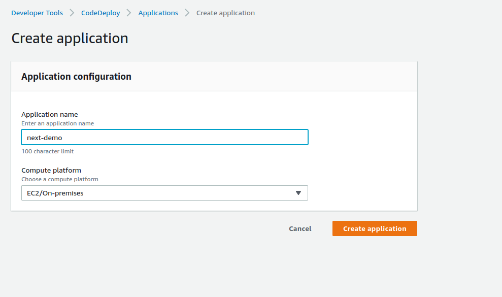
To use Code Deploy, We have to create an application first in the left hand side Deploy section.

Click on create Application.

11

You can choose a different computer platform as per your requirement.

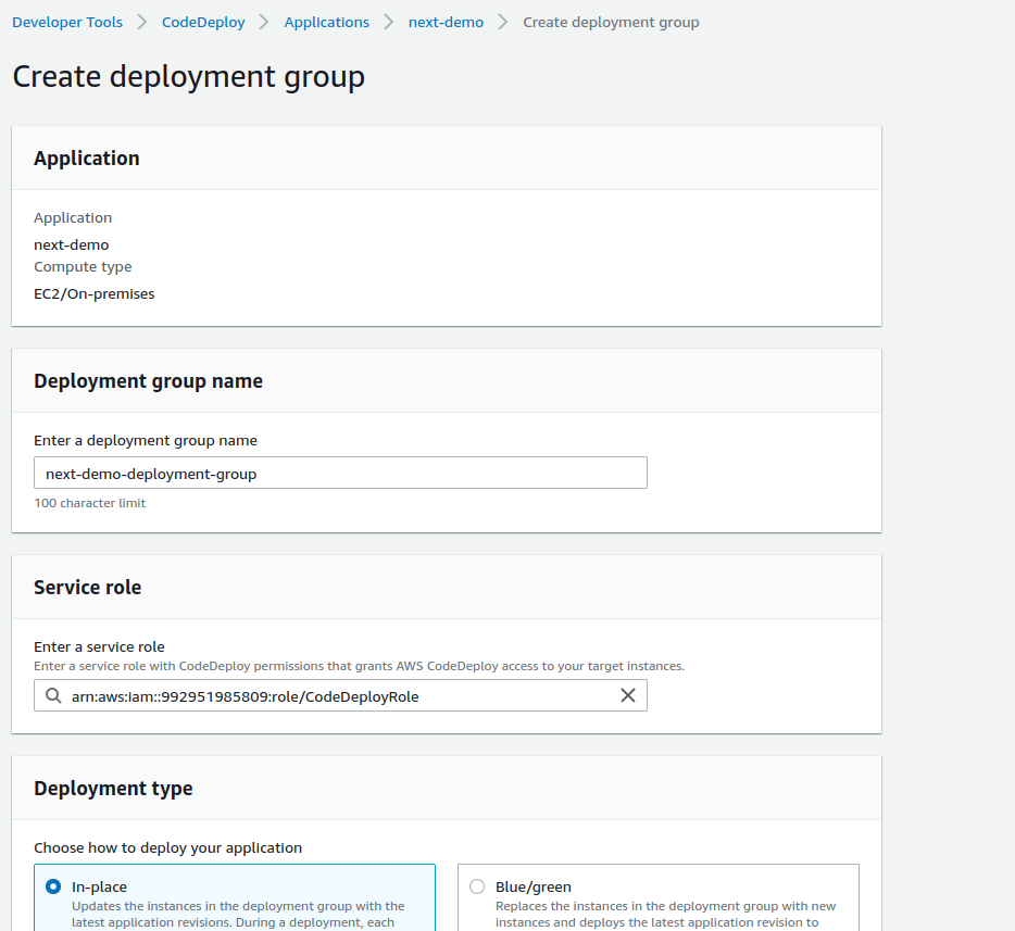
Once you create an application, Go to Deployment groups inside your newly created application.

Provide deployment group, And service role. Which should have access to codeDeploy.

CI-CD-2

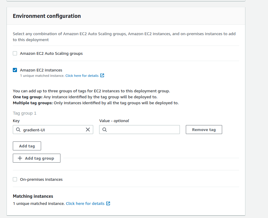
Choose Deployment Type. And In environment Configuration, Choose your appropriate option as per your requirement.

In Agent configuration with AWS Systems Manager, choose the option whether you want to allow the installation of the CodeDeploy Agent on all instances and update it based on the configured frequency.

CI-CD-3

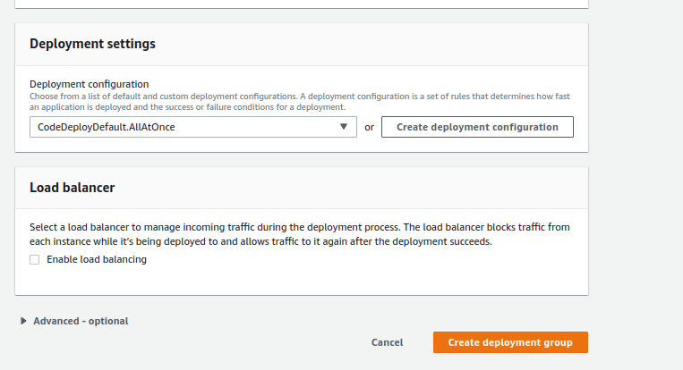
Choose deployment settings options. Disabled load balancer if you don’t want to manage incoming traffic during the deployment process.

CI-CD-4

Once you are all set, create a deployment group.

Now Let’s start with the Pipeline. To create a new pipeline, you can search the code pipeline in the AWS console search bar. Go to pipelines, and click on Create pipeline.

Pipeline settings

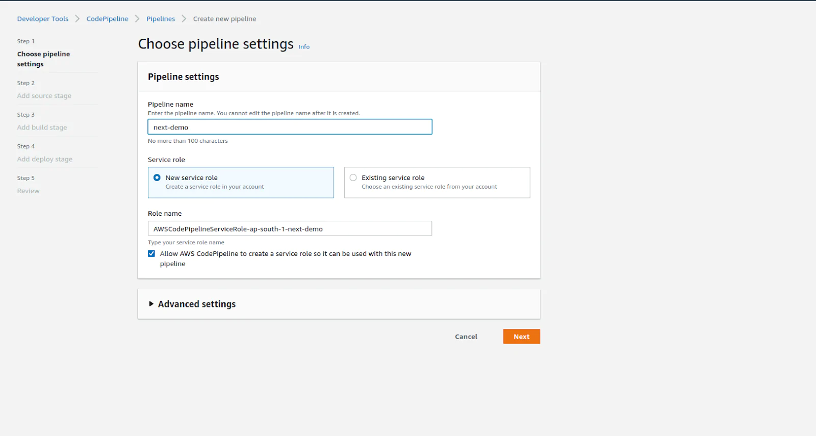
Enter your pipeline name (Generally your project name with environment), Allow AWS to create a new role or you can use an already existing role if created in AWS for pipeline.

CI-CD-5

Choose source provider

At this moment, AWS supports below source providers.

  • AWS code commit
  • Amazon ECR
  • Bitbucket
  • Github Version 1 (Not recommended method)
  • Github Version 2
  • Github Enterprise server

You can choose any of one option from the above options.For now, we are going with the Github Version 2.

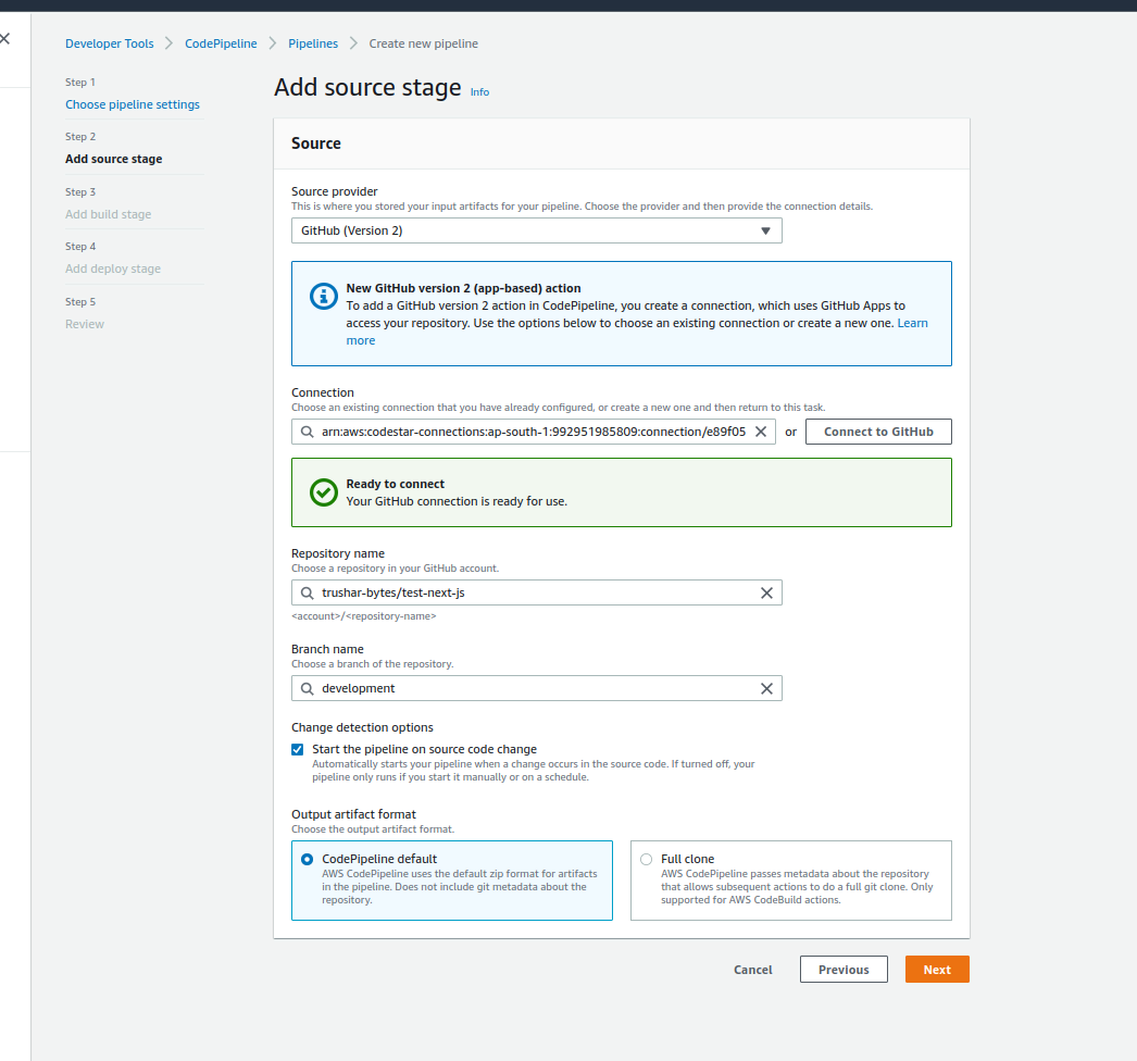
Connect your github account with Code pipeline to access your repo.

Once you are done with your connection you can choose which account you want to use with AWS.

Once you choose your github account. It will ask you for the repository name and branch name.

Click on the detection options if you want to trigger build every time. It means when any change occurs in a specific branch.

Choose appropriate artifact format and click on next.

CI-CD-6

Build stage

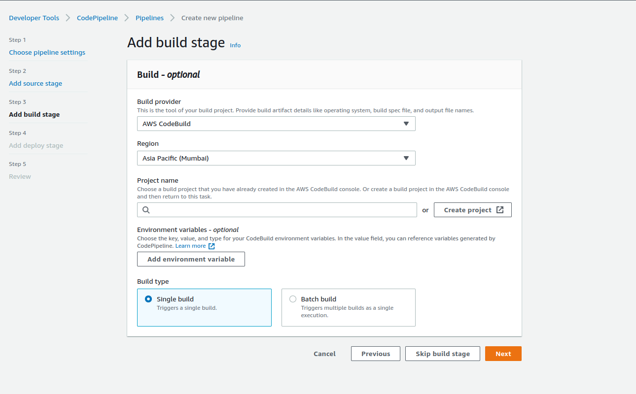
Choose the build stage, AWS code build or Jenkins. You can skip this stage if you want. You can add the build step at a later stage or already created pipeline also.

We will choose  the codeBuild. Select the region. Choose the build project if you have not created it.
CI-CD-7

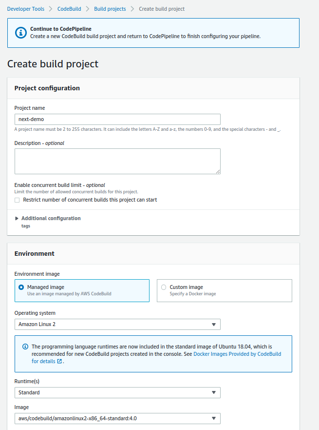
3.1 If you choose Create Project, it will open a popup,

3.1.1 Project configuration

Provide the project name, description and number of concurrent builds.

CI-CD-8

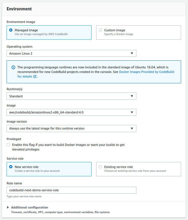
3.1.2  Environment

Choose the managed image or docker image. We will go with a managed image. In the service role, click new service role if you want to create new role or provide existing service role.

CI-CD-9

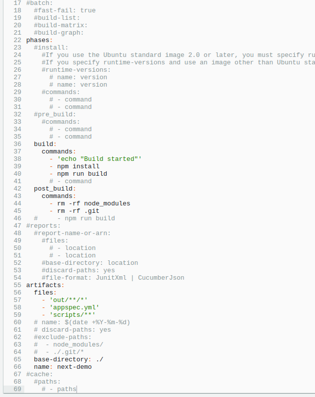
3.1.3 Buildspec option

Either you can use a buildspec file or can edit build commands. You can switch to editor also if you want to edit existing build commands.

We can provide our custom commands which is required at time of build or after build

CI-CD-10

Note: Make sure your artifacts are up to date. And your code should have an appspec.yml file. And in that file we can provide steps which we want to run. You can find more information in CodeDeploy AppSpec File reference.

Once you add the build project in the Build stage, click on next.

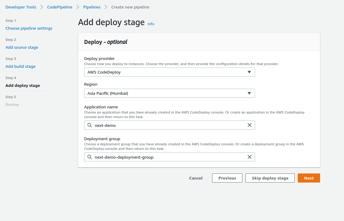
Choose the deployment stage

There are many deployment providers which AWS provides. For now, we are going with codeDeploy.

Choose your application and deployment group you want to go with.

CI-CD-11

Review

Review your all settings and if all is good, Hit Create pipeline.

Once you hit the create pipeline, It will immediately start the build process. And you can show the stages which we have added during pipeline creation.

This pipeline will run when any code changes when source changes.Which you have provided in codeBuild sections.

How To Deploy Web App From S3 Bucket To EC2 Instance on AWS Using CodePipeline


Overview Of CI/CD

AWS CI/CD architecture

Continuous Integration(CI) and Continous Deployment(CD) gets rid of the traditional manual gate and implements fully automated verification of the acceptance environment to determine the scenario whether the pipeline can continue to production or not.

Continuous Integration focuses on the software development life cycle (SDLC) of the individual developer in the code repository. This can be executed multiple times with a primary goal to enable early detection of integration bugs, and errors.

Continuous Delivery focuses on automated code deployment in testing or production environment, taking the approval of updates to achieve automated software release process, pre-emptively discovering deployment issues.

Check Out: AWS Inspector.

CI/CD Tools Offered By AWS Used In Case Study

AWS offers an end-to-end CI/CD stack comprised of the following four services:

AWS CodeCommit – It is a  fully-managed source control service that hosts secure Git-based repositories. CodeCommit makes it easy for teams to collaborate on code in a secure and highly scalable ecosystem.Code Commit

AWS CodeBuild – A fully managed continuous integration service that compiles source code, runs tests and produces software packages that are ready to deploy, on a dynamically created build server.
What is AWS CodeBuild? - AWS CodeBuild

Check out: AWS Storage overview and types of storage options offered what are they intended for.

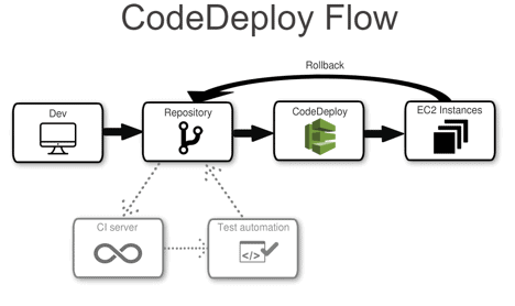
AWS CodeDeploy – A fully managed deployment service that automates software deployments to a variety of computing services such as Amazon EC2, AWS Fargate, AWS Lambda, and your on-premises servers.

aws-codedeploy-flow

AWS CodePipeline – A fully configured continuous delivery service that helps the user to automate their released pipelines for fast and reliable application and infrastructure updates.CI/CD Services Offered By AWS pipeline

Typically in many organizations, there are many tools for code repository but we are using AWS S3 as a code repository.

Check out: Amazon Elastic File System (EFS) what it is, its features, how it can be helpful.

Steps To Deploy Web Application Using AWS CodePipeline

We will be performing 4 steps to deploy a web application

Step 1: Create an S3 bucket for your application

Note: If you don’t have an AWS account check our blog on how to create AWS Free Tier Account.

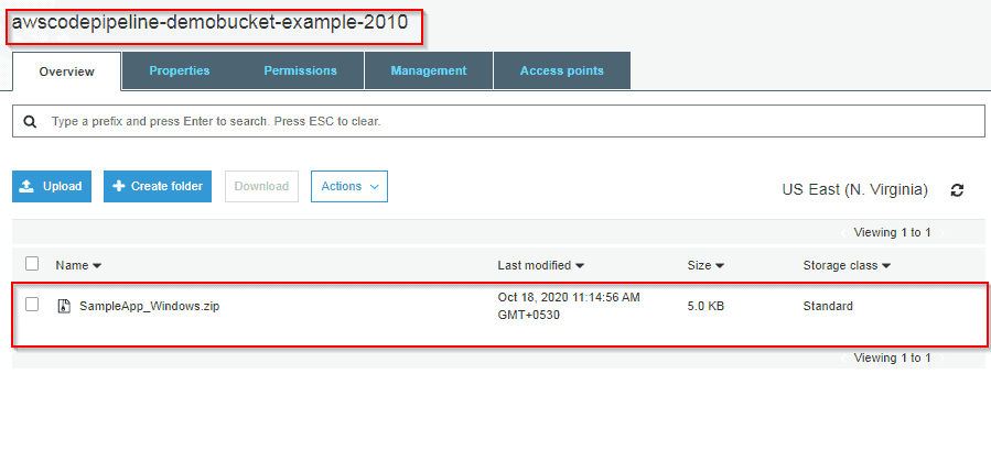
1) Open the Amazon S3 console and Choose Create bucket and In Bucket name, enter a name for your bucket, and also don’t forget to enable Versioning.

2) Next, download the sample code and save it into a folder or directory on your local computer.
Choose one of the following. Choose SampleApp_Windows.zip if you want to follow the steps in this tutorial for Windows Server instances. (Do not Unzip the file while Uploading)
–> If you want to deploy to Amazon Linux instances using CodeDeploy, download the sample application here: SampleApp_Linux.zip.
–> If you want to deploy to Windows Server instances using CodeDeploy, download the sample application here: SampleApp_Windows.zip.

3) In the S3 console, Upload code in the bucket you created.

AWS S3 Bucket

To Know More  About Blue-Green Deployment

Step 2: Create Amazon EC2 Windows instances and install the CodeDeploy agent

1) Create an IAM role that will be required to grant permission to EC2 instance. Select the policy named AmazonEC2RoleforAWSCodeDeploy to create.

Instance Role For EC2

2) Launch instance on which our code will be deployed.

3) Just remember to add the IAM role that we have created. and In Auto-assign Public IP, choose Enable. Expand Advanced Details, and in User data, As text selected, enter the following:
<powershell>
New-Item -Path c:\temp -ItemType “directory” -Force
powershell.exe -Command Read-S3Object -BucketName bucket-name/latest -Key codedeploy-agent.msi -File c:\temp\codedeploy-agent.msi
Start-Process -Wait -FilePath c:\temp\codedeploy-agent.msi -WindowStyle Hidden
</powershell>

Note: bucket-name is the name of the S3 bucket that contains the CodeDeploy Resource Kit files for your region. For example, for the US West (Oregon) Region, replace the bucket-name with AWS-code deploy-us-west-2. For a list of bucket names, see Resource Kit Bucket Names by Region.

4) On the Configure Security Group page, allow port 80 communication so you can access the public instance endpoint. Then follow the default configuration and launch the instance

Created EC2 instance

Also Check: Our blog post on SDLC Automation AWS

Step 3: Create an application in CodeDeploy

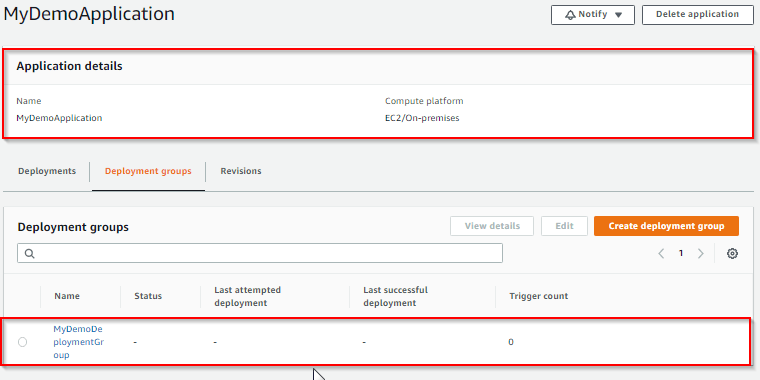
1) Initially create an application in CodeDeploy, and In Compute Platform, choose EC2/On-premises.Choose to Create application.

2) On the page that displays your application, choose to Create a deployment group. In service, role creates an IAM role under code deploy category. Under Deployment type, choose In-place.

3) Under Environment configuration, choose Amazon EC2 Instances.

4) Under Deployment configuration, choose CodeDeployDefault.OneAtaTime.

5) Under Load Balancer, clear Enable load balancing, leave the defaults then choose to Create a deployment group.

Application code deploy for CI/CD Services Offered By AWS

Also Check: Our blog post on AWS Certified DevOps Engineer Professional

Step 4: Create your first pipeline in CodePipeline

1) Open the CodePipeline console. Choose pipeline settings, Enter your desired name and in Service role, Choose New service role to allow CodePipeline to create a new service role in IAM.  To know more about AWS IAM refer to our blog on AWS Identity And Access Management (IAM).

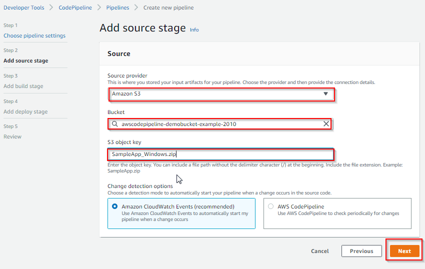
2) In the Add source stage, select Source provider, choose Amazon S3. Under the S3 object key, enter the object key with or without a file path, and remember to include the file extension.

3) In the Add build stage, choose to Skip build stage, and then accept the warning message by choosing Skip again. Choose Next.

4) In the Add deploy stage, in Deploy provider, choose AWS CodeDeploy.Then enter your application name or choose the application name from the list. In the Deployment group, enter MyDemoDeploymentGroup, or choose it from the list, and then choose Next.

AWS Pipeline

Congratulations! You just created a simple pipeline in CodePipeline. you can verify that by coping EC2 Public DNS address and then past it into the address bar of your web browser