Secured Virtual Hub Using Azure Firewall Manager
As businesses continue to migrate their operations to the cloud, it’s important to ensure that their assets and data are secure. One way to do this is by implementing a secured virtual hub in Microsoft Azure!
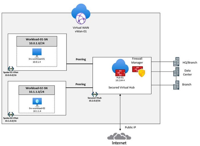
Azure Virtual WAN is a tool provided by Microsoft that allows you to build hub-and-spoke transitive architectures for establishing a connection point between your on-premises networks and the cloud. When security and routing policies are applied to this hub, it is called a secured virtual hub.
The secured virtual hub automatically routes traffic for you, eliminating the need for you to configure your own user-defined routes (UDRs) to filter and route traffic through your firewall. You have the option to select and integrate various security providers, including Azure Firewall or third-party security as a service (SECaaS) providers, to protect and control your network traffic.
In this article, we’ll take a look at how to set up a secured virtual hub using Microsoft Azure Firewall Manager coupled with the use of the Virtual WAN service. With Firewall Manager, you can define rules to allow or block traffic based on specific criteria, such as the source and destination of the traffic or the type of application being used, and centralize the management and administration of your defined security policies.
During this walkthrough, you will create spoke virtual networks and a virtual hub that they will connect and route traffic to. Next, you will deploy workload servers into the spoke networks, create a firewall policy to secure your virtual hub, and finally you will test the firewall!
We will accomplish this by completing the following list of tasks:

Step 1: Create two spoke virtual networks and subnets
In Step 1, we need to create two spoke virtual networks and subnets that will each host a workload server virtual machine.
a. Create Spoke Network 1 (Spoke-01-VNet)
From the Azure Portal, search for and select “virtual network” from the list of available services and then click on “Create”. We will begin by creating the first spoke virtual network by populating these fields with the information that follows:
- Subscription: select your subscription from the drop-down list
- Resource group: click on “Create new”, enter “fw-manager-rg” and then click on Save.
- Name: Spoke-01-VNet
- Region: East US
- Click on: Next: IP Addresses>

Next, we will define the IP address range and subnets for the Spoke-01-VNet by entering the following information:
- In the IPv4 address space field, modify the default address to 10.0.0.0/16 or enter any available network address range in your Azure environment.
- Next, click on the “default” subnet listed below and we will modify it to change it to the new information listed below. In the “Edit subnet” pop-out window, enter:
- Subnet name: Workload-01-SN
- Subnet address range: 10.0.1.0/24
Click on Save to accept the subnet configuration.


Click on “Review + Create” and then click on Create to begin the deployment of the Spoke-01-VNet and its subnet.

b. Create Spoke Network 2 (Spoke-02-VNet)
We will repeat the steps above to create a new spoke virtual network named Spoke-02-VNet which will be used to host a different workload server VM. Begin by searching for and selecting “virtual network” from the list of services at the top of the portal, then click on “Create”.
We will populate the required fields with the following information:
- Subscription: select your subscription from the drop-down list
- Resource group: click on “Create new”, enter “fw-manager-rg” and then click on Save.
- Name: Spoke-02-VNet
- Region: East US
- Click on: Next: IP Addresses>

Next, we will define the IP address range and subnets for the Spoke-02-VNet by entering the following information:
- In the IPv4 address space field, modify the default address to 10.1.0.0/16 or enter any available network address range in your Azure environment.
- Next, click on the “default” subnet listed below and we will modify it to change it to the new information listed below. In the “Edit subnet” pop-out window, enter:
- Subnet name: Workload-02-SN
- Subnet address range: 10.1.1.0/24
Click on Save to accept the subnet configuration.


Click on “Review + Create” and then click on Create to begin the deployment of the Spoke-02-VNet and its subnet.

Step 2: Create the secured virtual hub
In step 2, you will create a secured virtual hub using Firewall Manager. Search for and select “firewall manager” from the top search bar. On the Firewall Manager page, from the Overview page, click “View secured virtual hubs”. Next, click on “Create new secured virtual hub”

Next, we will enter the following information below to configure the virtual hub:
- Subscription: Select your subscription from the drop-down list
- Resource group: Select the firewall-manager-rg from the drop-down list
- Region: Select your region
- Secured virtual hub name: Hub-01
- Hub address space: 10.2.0.0/16
- Choose an existing vWAN or create a new one: Select “New vWAN”
- Virtual WAN Name: Vwan-01
Click Next: Azure Firewall >

Accept the defaults here and click on Next: Security Partner Provider > to advance to the next screen.

We will accept the default configuration here because we will not be setting up a connection to a Security Partner Provider here. Click on Next: Review + create >, and then click on “Create” to kick off the deployment of the Virtual Hub.

Once the Virtual Hub deployment has been completed on the Firewall Manager, we can navigate to the Hub’s Public IP configuration page to take note of its assigned public IP address. Click on click All services > type in “firewall manager” in the search box > click on Virtual Hubs > select Hub-01. Then, scroll down and click on the Public IP configuration option from the left side menu.
⚠ Take note of the Public IP address that has been assigned to the firewall’s Internet-facing interface. We will use this information later in step 5 when it is time to configure the firewall policies. It is 20.172.254.210 for this scenario.

Here are the current resources that have been created up to this point in our deployment:

Step 3: Connect the hub and spoke virtual networks
In Step 3, we will peer our spoke virtual networks to the hub by creating a connection. This peering relationship will allow traffic to flow between the spoke VNets and the Hub VNet. We can create this connection by navigating back to the Azure homepage and navigating to Resource groups > select the “fw-manager-rg” resource group, then select the Vwan-01 Virtual WAN.
Scroll down and click on “Virtual network connections” from the menu on the left side under the Connectivity section. Here, we find that our Hub-01 does not have any active connections to any networks. We will create one by clicking on + Add connection to add a connection from our Hub network to each of our spoke networks.

To create the connection between the Hub network and the Spoke-01 network, enter the following information into the required fields below:
- Connection name: hub-spoke-01
- Hubs: Hub-01
- Subscription: Select your subscription
- Resource group: fw-manger-rg
- Virtual network: select the Spoke-01-VNet
We will keep the default configurations for the remaining items and then click on “Create” to initiate the creation of this connection.

Next, we will repeat these steps to create a connection between the Hub and the Spoke-02 VNet by entering the following information into the required fields:
- Connection name: hub-spoke-02
- Hubs: Hub-01
- Subscription: Select your subscription
- Resource group: fw-manager-rg
- Virtual network: Spoke-02-VNet
We will keep the default configurations for the remaining items and then click on “Create” to initiate the creation of this connection.

With the creation of the connection completed, we can navigate back to the Virtual Network Connections page of the Virtual WAN and observe that we now have an active connection from Hub-01 to each of the spoke VNets, Spoke-01-VNet and Spoke-02-VNet.


Step 4: Deploy the virtual machine servers
In Step 4, we will deploy the virtual machine servers that will be used for the workloads on the spoke networks. We can deploy these using ARM templates that are available from the following Github repo: https://github.com/Nisha318/Azure-ARM-Templates/tree/main/Secured%20Virtual%20Hub
From the Azure portal, open a PowerShell session within the CloudShell pane. In the toolbar of the Cloud Shell pane, click on the “Upload/Download” files icon, in the drop-down menu, select Upload and upload the files FirewallManager.json and FirewallManager.parameters.json into the Cloud Shell home directory.
Execute the PowerShell cmdlet below to initiate the deployment of the ARM templates to create the VMs needed for this scenario.
Once the VM creation process has been completed, navigate back to the Azure portal to verify the status of the virtual machines.

From the top search bar, enter and select “virtual machines” and confirm that the two VMs are available and in a “Running” state.

Click on Srv-workload-01 VM and take note of the private IP address that has been assigned (10.0.1.4). We will need this information for the configuration of the firewall policy that we will configure in Step 5.

Click on Srv-workload-02 VM and take note of the private IP address that has been assigned (10.1.1.4). We will need this information for the configuration of the firewall policy that we will configure in Step 5.

Step 5: Create a firewall policy and secure your hub
With your firewall now set up, you can create rules to allow or block traffic based on your specific security needs. You can also use Firewall Manager to monitor traffic and detect potential threats, such as malware or suspicious activity.
In this step, we will first create the firewall policy on the Firewall manager and then use this policy to secure the hub. The firewall policy defines collections of rules to direct traffic for one or more Secured virtual hubs.

From the Azure portal homepage, click on All Services, then search for and click on Firewall Manager then click on Azure Firewall Policies.

From the Azure Firewall Policies page, click on + Create Azure Firewall Policy.
Here, we define a new policy for the firewall to which we will be able to add some rule collections and rules to control the routing of traffic on our networks. We will create a policy by entering the following information into the required fields below:
- Subscription: Select your subscription
- Resource group: select fw-manager-rg
- Name: Policy-01
- Region: Select your region
- Policy tier: Select Standard
Click on Next: DNS Settings > to advance to the next configuration tab

Accept the defaults here and click on Next: TLS Inspection > to advance to the next configuration tab.

Accept the defaults here and click on Next: Rules > to advance to the next configuration tab.

On the Rules tab, click on the + Add a rule collection button.

a. Add Application Rule Collection and Rules
The Application Rule will be created to allow traffic sourced from your virtual networks to reach specific FQDNs via the Internet. Unless traffic is explicitly configured to be allowed, the firewall will deny traffic, by default. In this case, we will create a rule to allow traffic routing to www.microsoft.com.
On the Add a rule collection page Enter the following information:
- Name: App-RC-01
- Rule collection type: Application
- Priority: 100
- Rule collection action: Allow
Rules:
- Name: Allow-msft
- Source type: IP Address
- Source: *
- Protocol: http,https
- Destination Type: FQDN
- Destination: *.microsoft.com
Click on Add

b. Add Destination Network Address Translation Collection and (DNAT) Rule
The purpose of our DNAT rule is to perform Network Address Translation so that any remote desktop connections (RDP) sourced from any IP address to a destination of the the firewall’s public IP address will have that destination IP address translated to be the private IP address for Srv-workload-01: 10.0.1.4. This way, we can connect to that virtual machine through the firewall. RDP uses port 3389 for connections.
Click on Add a rule collection where we will create a Destination NAT rule by entering the following information into the required fields below:
- Name: enter dnat-rdp
- Rule collection type: DNAT
- Priority: 100
Rules:
- Name: Allow-rdp
- Source type: IP Address
- Source: *
- Protocol: TCP
- Destination Port: 3389
- Destination: 20.172.254.210 (use the public IP of your firewall)
- Translated address or FQDN: enter the private IP address for Srv-workload-01: 10.0.1.4
- Translated port: 3389
Click on Add

c. Add Network Rule Collection and Rule
Next, we will add a Network rule so we can initiate a remote desktop connection from Srv-workload-01 to Srv-workload-02 VM. Click on + Add rule collection and enter the following information into the required fields below:
- Name: vnet-rdp
- Rule collection type: Network
- Priority: 100
- Rule collection action: Allow
Rules:
- Name: Allow-vnet
- Source type: IP Address
- Source: *
- Protocol: TCP
- Destination Ports: 3389
- Destination Type: IP Address
- Destination: 10.1.1.4
Click on “Add”

You should have 3 rules in place based on the configuration tasks provided in Step 5. With each of our desired firewall rule collections and rules in place, click on Review + create and then click on create to initiate the deployment of the Firewall Policy.

We have completed the steps needed to create a Firewall policy consisting of rule collect groups, collections, and rules.

Step 6: Associate the firewall policy
In Step 6, you will associate the firewall policy with the virtual hub. From the Azure portal homepage, click on Firewall Manager. Alternatively, you can find it by clicking on “All Services” and then searching for Firewall Manager.
On Firewall Manager, scroll down and click on Azure Firewall Policies under the Security section of the menu on the left side. Select the checkbox for Policy-01 and then click on Manage associations > Associate hubs on the menu bar.

Next, click on “Add” to accept this setting. This action will deploy the Azure Firewall into the selected hub.

After clicking on “refresh”, the association should now be displayed.
Step 7: Route traffic to your hub
In Step 7, we will configure the settings that will enable the virtual hub to manage the routing of network traffic to ensure that all get routed through the firewall.
On Firewall Manager, click on Virtual Hub > Hub-01. Click on Security configuration located under the Settings section of the left menu. Select the following configuration settings for Internet traffic and Private traffic so that all traffic will be directed to the Azure Firewall:
- In Internet traffic, select Azure Firewall.
- In Private traffic, select Send via Azure Firewall.

Click on OK to accept this change to the configuration.

Verify that the final configuration for Internet Traffic and Private Traffic, says “Secured by Azure Firewall”

Validation Testing
In this final stage of this deployment, you will test each of the configured firewall rules to validate that they are working as expected.
Step 8: Test the application rule
In this step, you will connect a remote desktop to the firewall's public IP address, which is NATed to the virtual machine named Srv-Workload-01. Once connected, you will then use a web browser on this server to test the application rule. Finally, you will connect a remote desktop to Srv-Workload-02 to test the network rule.
To begin this test, initiate an RDP connection from your local machine to the firewall’s public IP address by launching the Remote Desktop Connection tool. Enter the username and password that were supplied in the ARM template’s configuration file during the VM deployment. In this scenario, my firewall has a Public IP address of 20.172.254.210.

This will get us connected to the VM named Srv-Workload-01, as was configured by the DNAT rule that was configured on the firewall policy.


Once connected to the desktop of Srv-workload-01, launch the Internet Explorer browser and attempt to connect to www.microsoft.com in the address bar. Observe that this connection to the Microsoft site is successful and this is because you explicitly created an Application Rule in Step 5a to allow traffic to be routed to this FQDN. This test is successful!

Next, attempt a connection to an FQDN that has not been explicitly allowed by the creation of a firewall policy rule. Here, we observe an attempt to connect to www.google.com is blocked because there is no rule that was configured on the firewall to allow traffic to this FQDN. This test is successful and worked as expected.

Next, an attempt to connect to www.facebook.com is blocked as expected because there was no firewall wall configured to explicitly allow traffic to route to this FQDN. This test is successful and worked as designed!

Step 9: Test the network rule
In our final test, we will validate the Network Rules that were configured as part of the firewall policy. Launch the Remote Desktop Connection tool from virtual machine Srv-workload-01 to connect to Srv-workload-02 at IP address 10.1.1.4. Enter the credentials that were set in the ARM Template that was used for the deployment of the VMs.
Click on OK

Here, we observe that our connection to the virtual machine Srv-workload-02 at IP Address 10.1.1.4 is successful, thanks to the Network Rule that we configured as part of the firewall policy on Step 5c.

These validation tests validate that each of the configured firewall rules performed as expected. Just to explore a little further, we can also observe the currently set Effective Routes on the private network interfaces of the workload VMs that live on the Spoke and Hub networks.
Srv-workload-01 : Effective Routes
Observe that the Effective Routes table for the virtual machine Srv-workload-01 is set to route all RFC 1918 private address destined traffic to the private address of the virtual hub at 10.2.64.4. The default gateway is also set to direct any Internet-destined traffic to the hub as well using the default route of 0.0.0.0/0. All traffic is expected to route through the hub before being routed to any other destination.

Srv-workload-02 : Effective Routes
Observe that the Effective Routes table for the virtual machine Srv-workload-02 is set to route all RFC 1918 private address destined traffic to the private address of the virtual hub at 10.2.64.4. The default gateway is also set to direct any Internet-destined traffic to the hub as well using the default route of 0.0.0.0/0. All traffic is expected to route through the hub before being routed to any other destination.

Hub-01: Effective Routes
The Effective Routes of the Virtual Hub, Hub-01, is set to utilize the default route table which has all publicly and privately destined traffic to traverse the hub’s firewall as its next hop before continuing on to another destination.

No comments:
Post a Comment