How to Create and Configure VLANs on Cisco Switch with Packet Tracer
In a physical network environment, you can allocate users in a specific location to logical areas with VLANs. For example, if a 3-floor company has a finance department on each floor, you can configure a VLAN so that you can communicate these departments between floors.
In the actual scenario, users do not take notice of this change when you do this. By simply grouping the existing network logically, you get more network performance, and you can also restrict data traffic between VLAN groups.
You can now follow the steps below to create and configure VLANs on Switches using the simulator software.
Step 1
First, add a Router, Switch, and six PCs to the Packet Tracer workspace to create a network topology as shown in the image below.
Step 2
After configuring the Cisco Router’s interface and the TCP/IP settings of the computers, click Switch and click the CLI tab in the window that opens. To change to Privileged mode, execute enable.
Step 3
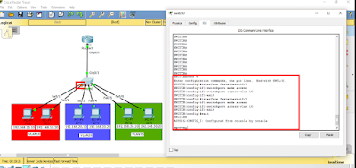
After making the basic settings, create 3 different VLAN groups according to the topology you have created on the Switch. Use the following commands to create a VLAN by topology.
Switch# conf t
Switch(config)# hostname SWITCH
SWITCH(config)# vlan 10
SWITCH(config-vlan)# name VLAN10
SWITCH(config-vlan)# exit
SWITCH(config)# vlan 20
SWITCH(config-vlan)# name VLAN20
SWITCH(config-vlan)# exit
SWITCH(config)# vlan 30
SWITCH(config-vlan)# name VLAN30
SWITCH(config-vlan)# exit
Step 4
After creating VLANs for departments, you need to make clients connected to the Switch interface to VLANs.
Switch from privileged configuration mode on Cisco Switch to global configuration mode.
To assign clients in the red zone to VLAN10, perform the following commands in order.
SWITCH# conf t
SWITCH(config)# interface fastethernet 0/1
SWITCH(config-if)# switchport mode access
SWITCH(config-if)# switchport access vlan 10
SWITCH(config-if)# exit
SWITCH(config)# interface fastethernet 0/2
SWITCH(config-if)# switchport mode access
SWITCH(config-if)# switchport access vlan 10
SWITCH(config-if)# exit
SWITCH(config)# end
Step 5
To assign clients in the blue zone to VLAN20, perform the following commands in order.
SWITCH# conf t
SWITCH(config)# interface fastethernet 0/3
SWITCH(config-if)# switchport mode access
SWITCH(config-if)# switchport access vlan 20
SWITCH(config-if)# exit
SWITCH(config)# interface fastethernet 0/4
SWITCH(config-if)# switchport mode access
SWITCH(config-if)# switchport access vlan 20
SWITCH(config-if)# exit
SWITCH(config)# end
Step 6
To assign clients in the green zone to the VLAN20, perform the following commands in order.
SWITCH# conf t
SWITCH(config)# interface fastethernet 0/5
SWITCH(config-if)# switchport mode access
SWITCH(config-if)# switchport access vlan 30
SWITCH(config-if)# exit
SWITCH(config)# interface fastethernet 0/6
SWITCH(config-if)# switchport mode access
SWITCH(config-if)# switchport access vlan 30
SWITCH(config-if)# exit
SWITCH(config)# end
Step 7
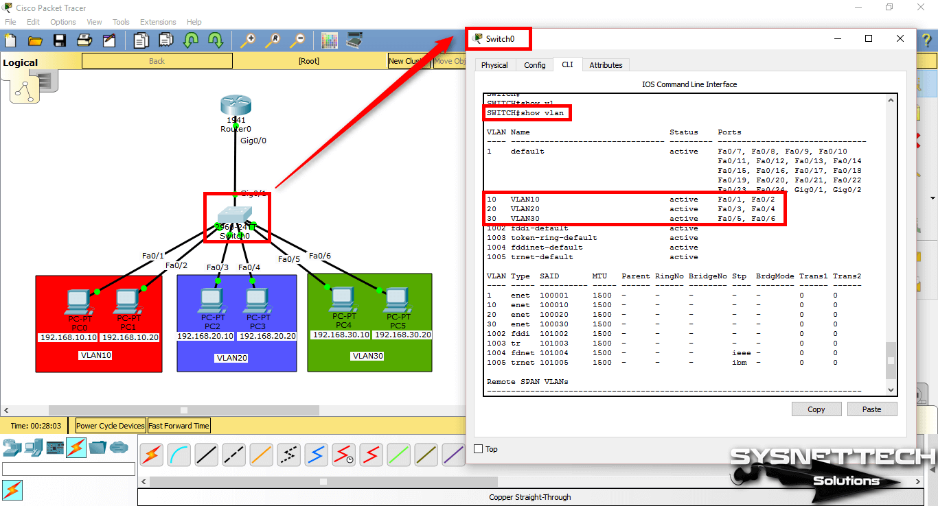
After adding the Switchport to the VLANs, check the interfaces you have created and made on the Switch with the show vlan command.
Step 8
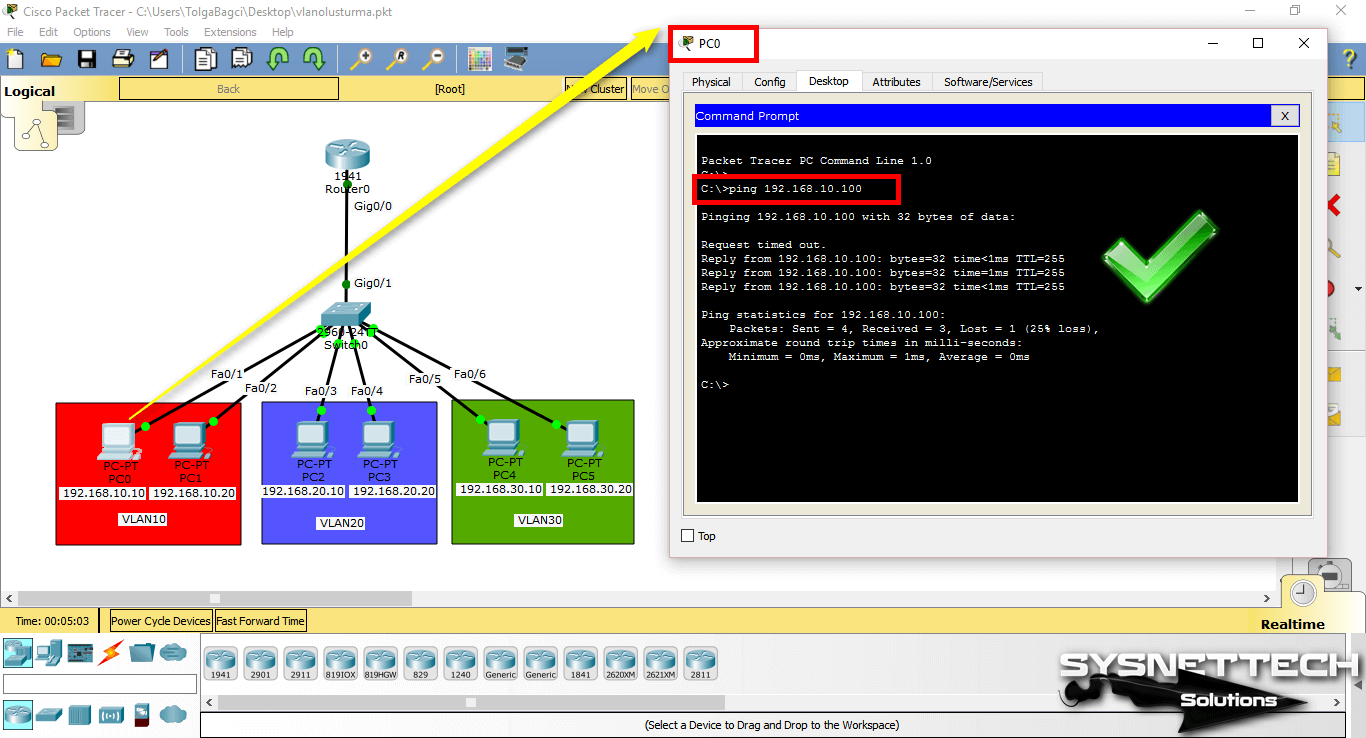
Since the network ports of PC0 and PC1 are connected to the VLAN10, you will see that there is a connection when you ping between these computers.
Step 9
When you ping between computers with other VLANs, you will see that the operation failed.
A ping test from PC0 to PC2 which is a member of VLAN20;
Step 10
When you ping PC4 from PC0 to VLAN30 member, ping will fail. The reason ping failed is that no routing has been made between the VLANs.
NOTE: When you configure VLANs on the Layer 2 switch, if there is a Router in the environment, you need to configure the Inter-VLAN.
Assigning a Management IP Address to VLANs
By granting a management IP address to VLANs, you can control your devices from the local or remote network.
The ip address command is used in the configuration mode of the port to assign an IP address to the interface of a router. In the Switch, this operation is performed in the settings of the VLAN you will assign IP.
A management IP can be assigned for each VLAN created.
To add management addresses for VLAN10, VLAN20, and VLAN30, addressing the network topology, follow these steps:
Step 1
In CLI, execute the configure terminal command and then the interface command (name of the vlan) to configure the corresponding VLAN.
SWITCH#conf t
Enter configuration commands, one per line. End with CNTL/Z.
SWITCH(config)#interface vlan 10
SWITCH(config-if)#
%LINK-5-CHANGED: Interface Vlan10, changed state to up
%LINEPROTO-5-UPDOWN: Line protocol on Interface Vlan10, changed state to up
SWITCH(config-if)#ip address 192.168.10.100 255.255.255.0
SWITCH(config-if)#no shutdown
SWITCH(config-if)#exit
SWITCH(config)#
SWITCH(config)#interface vlan 20
SWITCH(config-if)#
%LINK-5-CHANGED: Interface Vlan20, changed state to up
%LINEPROTO-5-UPDOWN: Line protocol on Interface Vlan20, changed state to up
SWITCH(config-if)#ip address 192.168.20.100 255.255.255.0
SWITCH(config-if)#no shutdown
SWITCH(config-if)#exit
SWITCH(config)#
SWITCH(config)#interface vlan 30
SWITCH(config-if)#
%LINK-5-CHANGED: Interface Vlan30, changed state to up
%LINEPROTO-5-UPDOWN: Line protocol on Interface Vlan30, changed state to up
SWITCH(config-if)#ip address 192.168.30.100 255.255.255.0
SWITCH(config-if)#no shutdown
SWITCH(config-if)#end
SWITCH#
Step 2
You can examine the IP addresses and port states of the interfaces with the show ip interface brief command in the switch.
Step 3
Pinging from PC0 to VLAN 10 management IP address (192.168.10.100) will be successful as follows.
Step 4
When you ping the VLAN 20 and VLAN 30 IP addresses (192.168.20.100 and 192.168.30.100) from PC0, the operation will fail.
Step 5
Finally, when you ping the management address from PC2, which is a member of VLAN20, the ping will succeed because clients that are members of the same VLAN can communicate.
If you ping the management address of the other VLAN, the operation will still fail.
Show Commands
SWITCH#show vlan
VLAN Name Status Ports
---- -------------------------------- --------- -------------------------------
1 default active Fa0/7, Fa0/8, Fa0/9, Fa0/10
Fa0/11, Fa0/12, Fa0/13, Fa0/14
Fa0/15, Fa0/16, Fa0/17, Fa0/18
Fa0/19, Fa0/20, Fa0/21, Fa0/22
Fa0/23, Fa0/24, Gig0/1, Gig0/2
10 VLAN10 active Fa0/1, Fa0/2
20 VLAN20 active Fa0/3, Fa0/4
30 VLAN30 active Fa0/5, Fa0/6
1002 fddi-default active
1003 token-ring-default active
1004 fddinet-default active
1005 trnet-default active
VLAN Type SAID MTU Parent RingNo BridgeNo Stp BrdgMode Trans1 Trans2
---- ----- ---------- ----- ------ ------ -------- ---- -------- ------ ------
1 enet 100001 1500 - - - - - 0 0
10 enet 100010 1500 - - - - - 0 0
20 enet 100020 1500 - - - - - 0 0
30 enet 100030 1500 - - - - - 0 0
1002 fddi 101002 1500 - - - - - 0 0
1003 tr 101003 1500 - - - - - 0 0
1004 fdnet 101004 1500 - - - ieee - 0 0
1005 trnet 101005 1500 - - - ibm - 0 0
Remote SPAN VLANs
------------------------------------------------------------------------------
Primary Secondary Type Ports
------- --------- ----------------- ------------------------------------------
SWITCH#
SWITCH#show vlan brief
VLAN Name Status Ports
---- -------------------------------- --------- -------------------------------
1 default active Fa0/7, Fa0/8, Fa0/9, Fa0/10
Fa0/11, Fa0/12, Fa0/13, Fa0/14
Fa0/15, Fa0/16, Fa0/17, Fa0/18
Fa0/19, Fa0/20, Fa0/21, Fa0/22
Fa0/23, Fa0/24, Gig0/1, Gig0/2
10 VLAN10 active Fa0/1, Fa0/2
20 VLAN20 active Fa0/3, Fa0/4
30 VLAN30 active Fa0/5, Fa0/6
1002 fddi-default active
1003 token-ring-default active
1004 fddinet-default active
1005 trnet-default active
SWITCH#
SWITCH#show running-config
Building configuration...
Current configuration : 1351 bytes
!
version 12.2
no service timestamps log datetime msec
no service timestamps debug datetime msec
no service password-encryption
!
hostname SWITCH
!
!
spanning-tree mode pvst
!
interface FastEthernet0/1
switchport access vlan 10
switchport mode access
!
interface FastEthernet0/2
switchport access vlan 10
switchport mode access
!
interface FastEthernet0/3
switchport access vlan 20
switchport mode access
!
interface FastEthernet0/4
switchport access vlan 20
switchport mode access
!
interface FastEthernet0/5
switchport access vlan 30
switchport mode access
!
interface FastEthernet0/6
switchport access vlan 30
switchport mode access
!
interface FastEthernet0/7
!
interface FastEthernet0/8
!
interface FastEthernet0/9
!
interface FastEthernet0/10
!
interface FastEthernet0/11
!
interface FastEthernet0/12
!
interface FastEthernet0/13
!
interface FastEthernet0/14
!
interface FastEthernet0/15
!
interface FastEthernet0/16
!
interface FastEthernet0/17
!
interface FastEthernet0/18
!
interface FastEthernet0/19
!
interface FastEthernet0/20
!
interface FastEthernet0/21
!
interface FastEthernet0/22
!
interface FastEthernet0/23
!
interface FastEthernet0/24
!
interface GigabitEthernet0/1
!
interface GigabitEthernet0/2
!
interface Vlan1
no ip address
shutdown
!
line con 0
!
line vty 0 4
login
line vty 5 15
login
!
end
SWITCH#
SWITCH#show ip interface brief
Interface IP-Address OK? Method Status Protocol
FastEthernet0/1 unassigned YES manual up up
FastEthernet0/2 unassigned YES manual up up
FastEthernet0/3 unassigned YES manual up up
FastEthernet0/4 unassigned YES manual up up
FastEthernet0/5 unassigned YES manual up up
FastEthernet0/6 unassigned YES manual up up
FastEthernet0/7 unassigned YES manual down down
FastEthernet0/8 unassigned YES manual down down
FastEthernet0/9 unassigned YES manual down down
FastEthernet0/10 unassigned YES manual down down
FastEthernet0/11 unassigned YES manual down down
FastEthernet0/12 unassigned YES manual down down
FastEthernet0/13 unassigned YES manual down down
FastEthernet0/14 unassigned YES manual down down
FastEthernet0/15 unassigned YES manual down down
FastEthernet0/16 unassigned YES manual down down
FastEthernet0/17 unassigned YES manual down down
FastEthernet0/18 unassigned YES manual down down
FastEthernet0/19 unassigned YES manual down down
FastEthernet0/20 unassigned YES manual down down
FastEthernet0/21 unassigned YES manual down down
FastEthernet0/22 unassigned YES manual down down
FastEthernet0/23 unassigned YES manual down down
FastEthernet0/24 unassigned YES manual down down
GigabitEthernet0/1 unassigned YES manual up up
GigabitEthernet0/2 unassigned YES manual down down
Vlan1 unassigned YES manual administratively down down
Vlan10 192.168.10.100 YES manual up up
Vlan20 192.168.20.100 YES manual up up
Vlan30 192.168.30.100 YES manual up up


No comments:
Post a Comment