Wednesday 10 July 2024

Deploy Azure Communications Gateway


Deploy Azure Communications Gateway

Prerequisites

Complete Prepare to deploy Azure Communications Gateway. Ensure you have access to all the information that you collected by following that procedure.

 Important

You must be a telecommunications operator to use Azure Communications Gateway.

For Operator Connect or Teams Phone Mobile, you must also have signed an Operator Connect or Teams Phone Mobile agreement with Microsoft. For more information on these programs, see Operator Connect or Teams Phone Mobile.

For Zoom Phone Cloud Peering, you must also have started the onboarding process with Zoom to become a Zoom Phone Cloud Peering provider. For more information on Cloud Peering, see Zoom's Cloud Peering information.

 Important

You must fully understand the onboarding process for your chosen communications service and any dependencies introduced by the onboarding process.

Allow sufficient elapsed time for the deployment and onboarding process. For example, you might need wait up to two weeks for a new Azure Communications Gateway resource to be provisioned before you can connect it to your network.

You must own globally routable numbers for two types of testing:

  • Integration testing by your staff during deployment and integration
  • Service verification (continuous call testing) by your chosen communication services

The following table describes how many numbers you need to allocate.

ServiceNumbers for integration testingService verification numbers
Operator Connect1 (minimum)- Production deployments: 6
- Lab deployments: 3
Teams Phone Mobile1 (minimum)- Production deployments: 6
- Lab deployments: 3
Microsoft Teams Direct Routing1 (minimum)None (not applicable)
Zoom Phone Cloud Peering1 (minimum)- US and Canada: 6
- Rest of world: 2
Azure Operator Call Protection Preview1 (minimum)None (not applicable)

 Important

Service verification numbers must be usable throughout the lifetime of your deployment.

Create an Azure Communications Gateway resource

Use the Azure portal to create an Azure Communications Gateway resource.

  1. Sign in to the Azure portal.

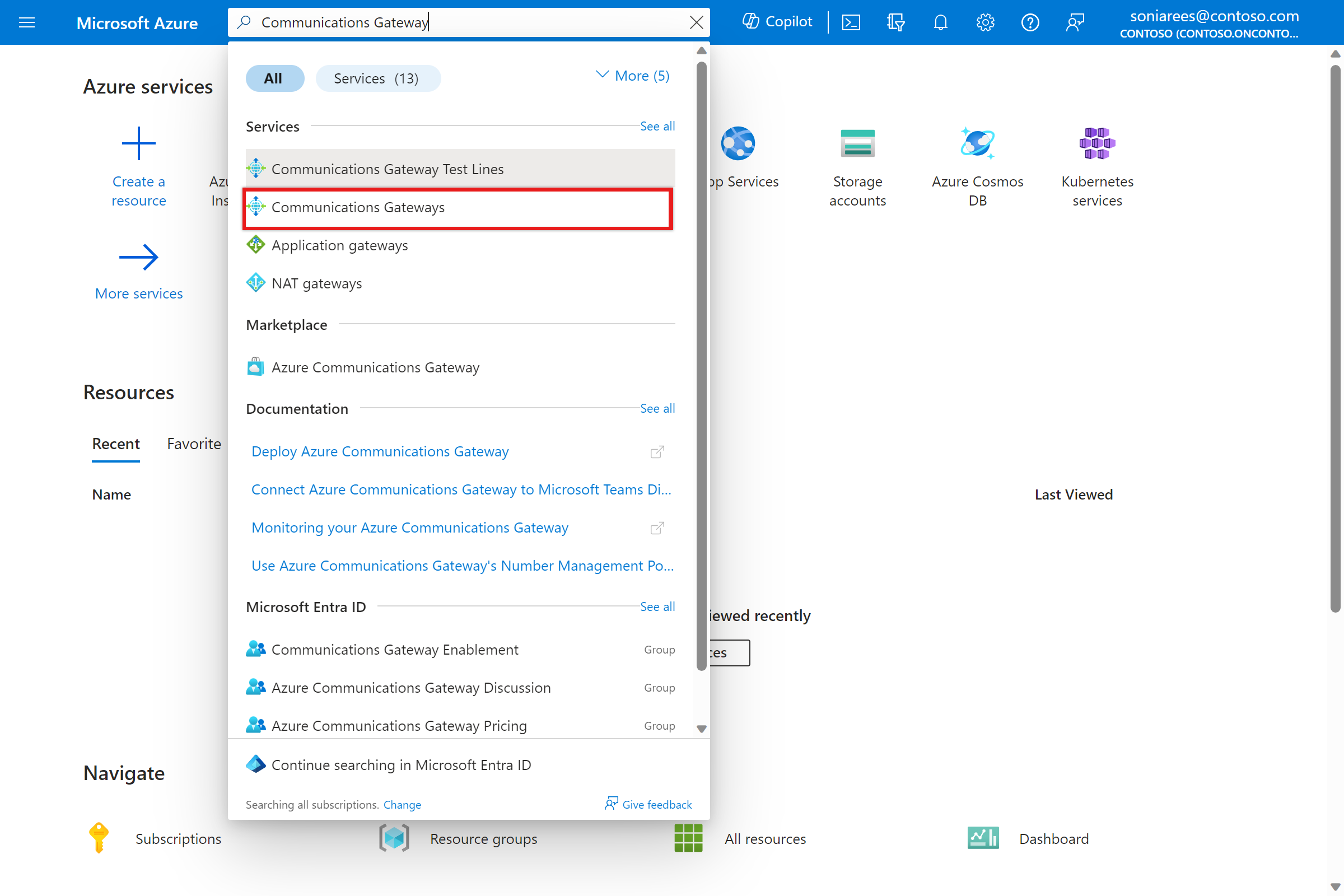
  2. In the search bar at the top of the page, search for Communications Gateway and select Communications Gateways.

    Screenshot of the Azure portal. It shows the results of a search for Azure Communications Gateway.

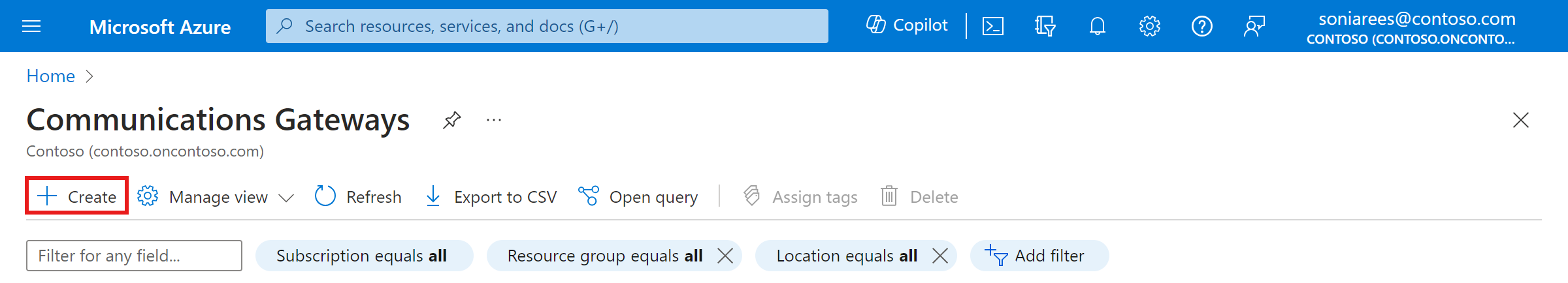
  3. Select the Create option.

    Screenshot of the Azure portal. Shows the existing Azure Communications Gateway. A Create button allows you to create more Azure Communications Gateways.

  4. Use the information you collected in Collect basic information for deploying an Azure Communications Gateway to fill out the fields in the Basics configuration tab and then select Next: Service Regions.

  5. Use the information you collected in Collect configuration values for service regions to fill out the fields in the Service Regions tab and then select Next: Communications Services.

  6. Select the communications services that you want to support in the Communications Services configuration tab, use the information that you collected in Collect configuration values for each communications service to fill out the fields, and then select Next: Test Lines.

  7. Use the information that you collected in Collect values for service verification numbers to fill out the fields in the Test Lines configuration tab and then select Next: Tags.

    • Don't configure numbers for integration testing.
    • Microsoft Teams Direct Routing and Azure Operator Call Protection Preview don't require service verification numbers.
  8. (Optional) Configure tags for your Azure Communications Gateway resource: enter a Name and Value for each tag you want to create.

  9. Select Review + create.

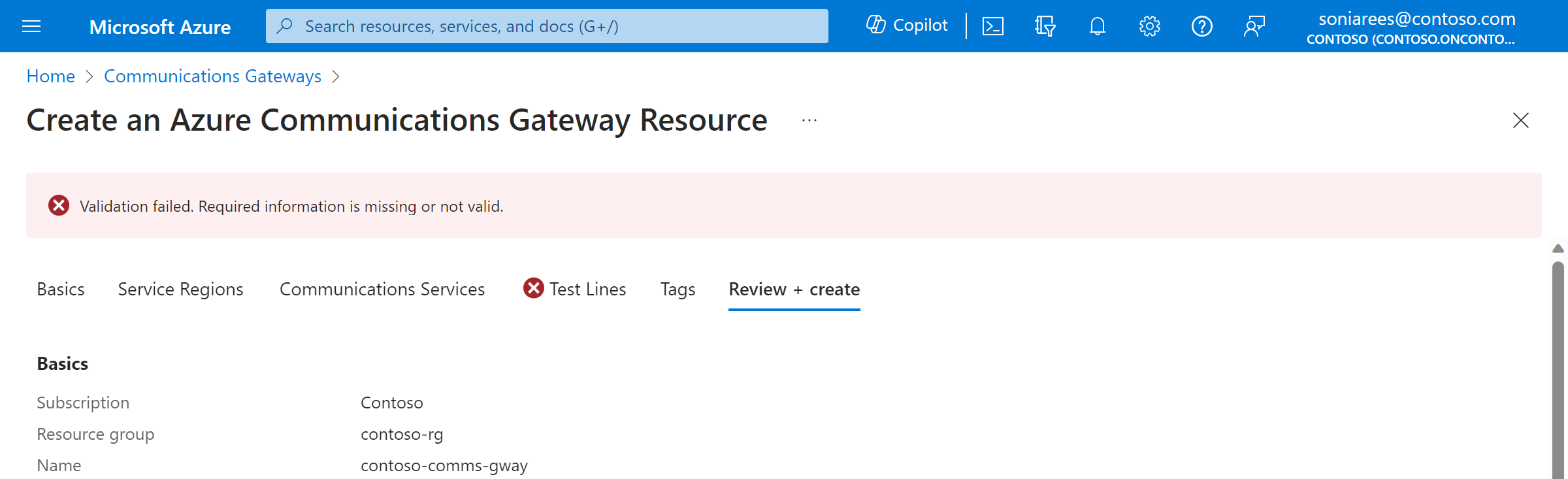
If you've entered your configuration correctly, the Azure portal displays a Validation Passed message at the top of your screen. Navigate to the Review + create section.

If you haven't filled in the configuration correctly, the Azure portal display an error symbol for the section(s) with invalid configuration. Select the section(s) and use the information within the error messages to correct the configuration, and then return to the Review + create section.

Screenshot of the Create an Azure Communications Gateway portal, showing a validation that failed due to missing information in the Contacts section.

Submit your Azure Communications Gateway configuration

Check your configuration and ensure it matches your requirements. If the configuration is correct, select Create.

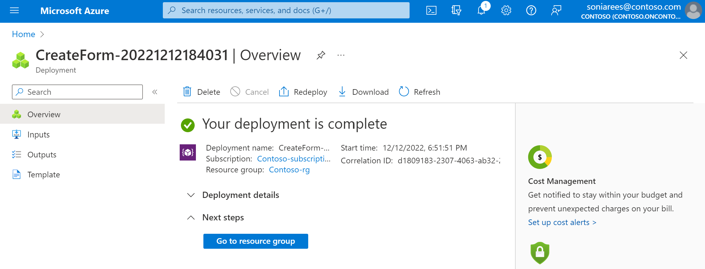
Once your resource has been provisioned, a message appears saying Your deployment is complete. Select Go to resource group, and then check that your resource group contains the correct Azure Communications Gateway resource.

 Note

You can't make calls immediately. You need to complete the remaining steps in this guide before your resource is ready to handle traffic.

Screenshot of the Create an Azure Communications Gateway portal, showing a completed deployment screen.

Wait for provisioning to complete

Wait for your resource to be provisioned. When your resource is ready, the Provisioning Status field on the resource overview changes to "Complete." We recommend that you check in periodically to see if the Provisioning Status field is "Complete." This step might take up to two weeks.

Connect Azure Communications Gateway to your networks

When your resource has been provisioned, you can connect Azure Communications Gateway to your networks.

  1. Exchange TLS certificate information with your onboarding team.
    1. Azure Communications Gateway is preconfigured to support the DigiCert Global Root G2 certificate and the Baltimore CyberTrust Root certificate as root certificate authority (CA) certificates. If the certificate that your network presents to Azure Communications Gateway uses a different root CA certificate, provide your onboarding team with this root CA certificate.
    2. The root CA certificate for Azure Communications Gateway's certificate is the DigiCert Global Root G2 certificate. If your network doesn't have this root certificate, download it from https://www.digicert.com/kb/digicert-root-certificates.htm and install it in your network.
  2. Configure your infrastructure to meet the call routing requirements described in Reliability in Azure Communications Gateway.
    • Depending on your network, you might need to configure SBCs, softswitches, and access control lists (ACLs).

     Important

    When configuring SBCs, firewalls, and ACLs, ensure that your network can receive traffic from both of the /28 IP ranges provided to you by your onboarding team because the IP addresses used by Azure Communications Gateway can change as a result of maintenance, scaling or disaster scenarios.

    • If you are using Azure Operator Call Protection Preview, a component in your network (typically an SBC), must act as a SIPREC Session Recording Client (SRC).
    • Your network needs to send SIP traffic to per-region FQDNs for Azure Communications Gateway. To find these FQDNs:
      1. Sign in to the Azure portal.
      2. In the search bar at the top of the page, search for your Communications Gateway resource.
      3. Go to the Overview page for your Azure Communications Gateway resource.
      4. In each Service Location section, find the Hostname field. You need to validate TLS connections against this hostname to ensure secure connections.
    • We recommend configuring an SRV lookup for each region, using _sip._tls.<regional-FQDN-from-portal>. Replace <regional-FQDN-from-portal> with the per-region FQDNs from the Hostname fields on the Overview page for your resource.
  3. If your Azure Communications Gateway includes integrated MCP, configure the connection to MCP:
    1. Go to the Overview page for your Azure Communications Gateway resource.
    2. In each Service Location section, find the MCP hostname field.
    3. Configure your test numbers with an iFC of the following form, replacing <mcp-hostname> with the MCP hostname for the preferred region for that subscriber.
      XML
      <InitialFilterCriteria>
          <Priority>0</Priority>
          <TriggerPoint>
              <ConditionTypeCNF>0</ConditionTypeCNF>
              <SPT>
                  <ConditionNegated>0</ConditionNegated>
                  <Group>0</Group>
                  <Method>INVITE</Method>
              </SPT>
              <SPT>
                  <ConditionNegated>1</ConditionNegated>
                  <Group>0</Group>
                  <SessionCase>4</SessionCase>
              </SPT>
          </TriggerPoint>
          <ApplicationServer>
              <ServerName>sip:<mcp-hostname>;transport=tcp;service=mcp</ServerName>
              <DefaultHandling>0</DefaultHandling>
          </ApplicationServer>
      </InitialFilterCriteria>
      
  4. Configure your routers and peering connection to ensure all traffic to Azure Communications Gateway is through Microsoft Azure Peering Service Voice (also known as MAPS Voice) or ExpressRoute Microsoft Peering.
  5. Enable Bidirectional Forwarding Detection (BFD) on your on-premises edge routers to speed up link failure detection.
    • The interval must be 150 ms (or 300 ms if you can't use 150 ms).
    • With MAPS Voice, BFD must bring up the BGP peer for each Private Network Interface (PNI).
  6. Meet any other requirements for your communications platform (for example, the Network Connectivity Specification for Operator Connect or Teams Phone Mobile). If you need access to Operator Connect or Teams Phone Mobile specifications, contact your onboarding team.

Configuring Windows Server Hyper-V and Virtual Machines


Virtual networks

Virtual networks allow the virtual machine to communicate with the rest of your network, the host machine, and other virtual machines. With the Virtual Network Manager, you can create the following types of virtual networks:

Private network—allows a virtual machine to communicate only with another virtual machine on the host.

Internal network—sets up communication between the host system and the virtual machines on it.

External network—connects virtual machines and the host physical network. This allows the virtual machine to communicate on the same network as the host, operating as any other node on the network.

1.

You can create and manage virtual networks by clicking on the Virtual Network Manager link on the right-hand page (as shown in Figure 4.2). This brings up a wizard similar to the one shown in Figure 4.3.

▪ Figure 4.2. Launching the Virtual Network Manager.

▪ Figure 4.3. Virtual Network Manager Wizard.

2.

In this case, you want your new virtual machine to talk on your network, so you will select External and click Add (see Figure 4.3).

3.

Give the virtual network a name, one that is easy to identify. The notes field can also help to identify the virtual network's intended function. On the Connection type, you should choose External, since you want to use it to connect to your physical network in the lab. You have to choose a physical network card in the host server from the drop-down box (remember to leave one card dedicated to management!), and finally you have the option to enable Virtual LAN identification, with the number of the VLAN you want to use (see Figure 4.4). Virtual LANs are used as a security control to segment data within a switched network; discussion of the pros and cons of VLANs are beyond the scope of this book.

▪ Figure 4.4. Creating the Virtual Network.

4.

You acknowledge the warning in the pop-up shown in Figure 4.5 and click Yes. (If, by now, you have seen this pop-up window more times than you can remember, you can check the box to never be asked again. Just do not be surprised when you lose your network connection on that card temporarily!)

▪ Figure 4.5. Network Warning.

Remember when we told you to dedicate a network card to managing the server? If you decided against that, and are using remote desktop to manage the Hyper-V server, you just lost your connection for a short while. Do not panic; it will be back soon.

Now that you have created your virtual network, you can use the same Virtual Network Manager to change it to an Internal or Private network. Simply select the proper radio button, as shown in Figure 4.4.

Note

Internal Networks may also use VLAN identification. Private Networks do not—they are only used for virtual machine to virtual machine communication.

Now that you have a network, you can use it when you create your first virtual machine. The creation of virtual machines is covered in Chapter 7.


Building penetration test labs


Virtual networks

Another part of virtualization is the virtual network associated with the virtual machines. Since they are using one or more virtual network cards, those virtual cards may or may not be configured to interact with a physical network card on the host machine. The hypervisor can create a virtual network that allows the guest operating systems to communicate with each other as if they were on a physical network without actually needing to have that network hardware present. For example, a virtual switch can be set up with all of the virtual network cards for multiple guest OSs connected to it. This would allow the virtual systems to communicate with each other, but nothing else.

This is an important part of the security within a virtualized environment and is very applicable to your work with penetration testing. By creating a virtual network and keeping it isolated to the virtual machines running on the host, you can create an environment that simulates network communication without actually risking the possibility of those virtual machines connecting to your actual physical network.

In addition, there is now an effort to create virtual networks that are not necessarily just for connecting virtual hosts together. Software Defined Networks (SDNs) are beginning to become mainstream and are available through multiple vendors. We’ll discuss some of the tools for this in the “Open Source Tools” section, but for now you should be aware that developers are creating virtualization software which allows you to simulate entire networks within a virtual environment. This includes objects such as switches, routers, and VPNs.

By virtualizing networks in this manner, you can create a safe, isolated environment for simulating all sorts of network behavior. From the penetration tester’s point of view, this can give us a playground for testing network devices or performing attacks such as ARP poisoning without impacting actual physical networks.


Designing your virtual network

The introduction to Hyper-V discussed several different types of networks available to a virtual machine. These different networks give us some flexibility in designing our enterprise for security as well as performance.

Remember that when you create a virtual machine, you have the option of creating three different types of virtual networks: External, which connects a virtual machine to the physical network; Internal, which allows virtual machines on the same host to communicate with each other, and with the management OS; and Private, which only allows virtual machines on the same host to communicate with each other. What does this mean to you? Imagine for a moment a typical web store, with purchasing and item data kept on a SQL server, and the Web site itself running on IIS. In a virtual environment, you might set it up similar to Figure 9.1.


By using a combination of private and external networks, you are able to create a site that is much more resistant to attack, by removing the database server from the external network entirely, allowing it to communicate only with the IIS server.


A survey on data center networking for cloud computing

Bin Wang, ... Athanasios V. Vasilakos, in Computer Networks, 2015

5.3.1 VDC and virtual network

VDC and virtual network are complementary concepts that do not depend on each other. Unlike a virtual network, a VDC-based network does not use 2 or 3 layer techniques to build privileged communications among different VMs. Instead, a VM and a neighbor in the same VDC can be physically remote provided the two VMs are placed in a way that allows them to attain sufficient resources. Similarly, in the context of a virtual network, the address of each VM must be either overwritten across the physical infrastructure or encapsulated in the packet header, while a VDC-based network does not provide any address restriction to the member VMs [12,73]. Moreover, the communication elements in a virtual network include not only the VM but also the physical server and switch, while a VDC only guarantees resources for VMs.


Quantifying IT Energy Efficiency


4.2.2 Network Layer

Similarly to system virtualization, it is possible to virtualize whole networks. From the perspective of the network layer, a virtualized network consists of virtual routers and virtual links. Virtual routers are interconnected by virtual links. The mapping of the virtual network to the physical substrate is done by assigning to each virtual router one or even multiple physical routers. Also, the virtual links between virtual routers have to be mapped to the physical substrate network. It is common that a virtual link is mapped to a path in the substrate network with a path length longer than one.

In Fig. 7, a physical and two virtual networks are depicted. The physical network consists of seven interconnected physical routers, numbered from 1 to 7. Virtual Network 1 consists of the virtual routers ABC, and D that are interconnected by virtual links. In the given example, each virtual router of Virtual Network 1 is mapped to one physical router: A is mapped to 1, B is mapped to 3, C is mapped to 5, and D is mapped to 7. Furthermore, the embedding of Virtual Network 1 illustrates that virtual links can be mapped to multiple physical links. The virtual link 𝐵𝐶 between the virtual routers B and C is mapped to the path 3645 in the physical network. Another possibility to map the virtual link 𝐵𝐶 would be the physical path 345Virtual Network 2 consists of the virtual routers 𝑎𝑏, and c, and the virtual links 𝑎𝑏 and 𝑏𝑐. The virtual link 𝑎𝑏 is mapped to the physical link 12 whereas the virtual link 𝑏𝑐 is mapped to 57. In contrast to Virtual Network 1, in Virtual Network 2 the virtual router b is mapped to multiple physical routers, to the routers 2, 4, and 5, in the substrate network. Furthermore, the example in Fig. 7 shows the possibility of consolidating multiple virtual routers on the same physical router. For instance, the virtual routers a and A are both consolidated on the physical router 1.

Fig. 7. Energy-efficient mapping of virtual networks.

The virtualization of networks allows for a dynamic reallocation of physical resources in a transparent way. This flexibility can be used to increase the energy efficiency of the network. In times of low network traffic underutilized virtual routers can be consolidated on the same physical router allowing for shutting down unused physical routers. When the load on the virtual routers increases, physical routers can be powered on again and the virtual routers are migrated back. Similarly, when a virtual router is mapped to multiple physical routers, at times of low traffic a part of the physical routers can be turned off or hibernated, leaving only a minimum number of physical routers powered on. Also the mapping of virtual links leaves room for optimizing network energy consumption. An energy-aware mapping of virtual routers and virtual links allows for shutting down parts of the physical infrastructure when not needed. In times of low network traffic, multiple virtual links can be mapped to the same physical link or path respectively. This enables bypassing single physical routers that can be turned off or hibernated.


A survey on data center networking for cloud computing


5.2.4 Virtual network

The evolution of virtual networks can be characterized by two distinct time periods in which it has existed. The first is the pre-cloud period, during which time cloud computing had not yet been proposed. Techniques such as Virtual Local Area Networks (VLAN) [69] and Virtual Private Networks (VPN) [69] existed then, supported by almost all current layer 3 switches. However, virtual networks at this time could not fulfill large-scale demands for groups because they were still coupled with physical networks. The second period is post-cloud, when cloud computing became prevalent. To accommodate large numbers of virtual networks, techniques such as VXLAN [70], NVGRE [71] were proposed. In addition, techniques during this period, such as Contrail [59], have prioritized improved management and independence from their physical network.

VLAN provides logical isolation between broadcast domains at layer 2 by creating virtual networks. Multiple VLANs are bounded by differing segments [69]. The primary function of VLAN is to ensure that all the virtual networks are able to share the same physical infrastructure while being properly segmented. VLAN!‘®s main advantage is its ability to isolate tenants’ logical networks. However, because of the limited size of its segment (12 bits,) it is only able to create 4096 virtual networks.

VXLAN employs tunneling via MAC-in-UDP [63] to restrict packets in the destinations net segment. By using UDP multicast instead of broadcast, VXLAN significantly improves the migration performance among data centers while balancing the tradeoff with local broadcast. Moreover, VXLAN enables the cloud to create more virtual networks due to its larger segment address size (24 bits). The drawbacks of VXLAN include the requirement of layer 3 device support and the latency associated with long distances in a virtual network.

NVGRE applies GRE as a method to tunnel layer 2 packets across an IP network, and uses 24 bits of the GRE key as a logical network discriminator. The broadcast of the virtual network is achieved through physical multicast.

Contrail supports virtual networking using SDN-based virtualization, in which a controller can reset different encapsulation approaches in order to manage different layers virtual networks, e.g., layers 2 and 3 VPNs. The main functions of Contrail include abstracting network control into different layers, providing APIs to different versions of devices, and isolating tenants in the cloud.

Table 3 compares the existing virtual network techniques surveyed in this paper. In terms of their encapsulation, VLAN is the first that uses encapsulation technique to isolate different virtual networks. However, VXLAN and NVGRE employ faster tunnels for encapsulation than VLAN, because both UDP [72] and GRE perform better than IP in VM migration. An OpenFlow controller enables Contrail and NSX to manage common issues by monitoring VM flows and configuring different routing protocols. Column 5 shows the maximum number of virtual networks that a scheme scales. VLAN,and Contrail have a 12 bit segment which virtualizes up to 212 virtual networks. VXLAN achieves high scalability by extending the segment size to 24 bits. All the techniques in the table except VLAN support multi-tenants, due to their cloud computing-optimized designs.

Table 3. Comparison of different virtual networks in the DCN.

Virtual networksDetailed descriptionEncapsulationPacker headerMaximum VNsMultiple tenants
VLAN [69]Bridging different VMs and bounding the virtual network by differing segmentMAC-in-IP12 bits VLAN segment212×
VXLAN [70]Using UDP multicast instead of broadcast at layer 2MAC-in-UDPExtending segment size from VLAN224
NVGRE [71]Using 24 bits of the GRE key as a logical network discriminatorMAC-in-GREExtending segment size from VLAN224
Contrail [59]OpenFlow controller to manage the virtual networkMAC-in-UDP, MAC-in-IPOpenFlow segment bits212

Hyper-V feature focus

Dustin Hannifin, ... Joey Alpern, in Microsoft Windows Server 2008 R2, 2010

Administering virtual networks

At some point, you may need to add additional virtual networks or make changes to existing networks. As mentioned earlier, virtual networks provide networking services to VMs. Hyper-V supports the following virtual network types in which VMs can connect:

External—An external virtual network uses the physical computer's network adapter to bridge the virtual network with the physical network. This gives VMs network access just as if they were a physical computer plugged into a network switch.

Internal—An internal virtual network isolates VMs so that they can only talk to other VMs on the Hyper-V server, and the Hyper-V server itself. Using this setting prevents VMs from communicating with the physical network.

Private—A private virtual network isolates the VMs so that they can only communicate with each other. Using this network prevents them from communicating with the Hyper-V host or physical network.

You can manage virtual network settings by performing the following:

1.

Open Server Manager and select the node Roles | Hyper-V | Hyper-V Manager | <YourServerName>.

2.

Right click the server name (see Figure 7.7) and choose the Virtual Network Manager option.

Figure 7.7. Hyper-V manager.

3.

The Virtual Network Manager window will open (see Figure 7.8). Here you can add or remove virtual networks as well as make configuration changes to existing ones.

Figure 7.8. Virtual network manager.

You can use Virtual Network Manager, as seen in Figure 7.9, to configure the following settings for existing virtual networks:


Name and notes—You can enter a meaningful name and notes related to the Virtual Network connection. The virtual network name should be something that helps you easily identify that particular network.

Connection type—Here you can change the connection type to any of the three supported network types.

Enable VLAN identification—If you use VLAN tagging on your network, you can have Hyper-V's virtual network tag traffic so it knows which VLAN it should be part of.

Notes from the field

Virtual Network MAC address range

You can use Virtual Network Manager to manage the range of MAC addresses that Hyper-V will assign to VMs. In most cases, you will not need to change this range. If you do however change the range of hardware addresses, be sure that they do not conflict with existing MACs on your network.